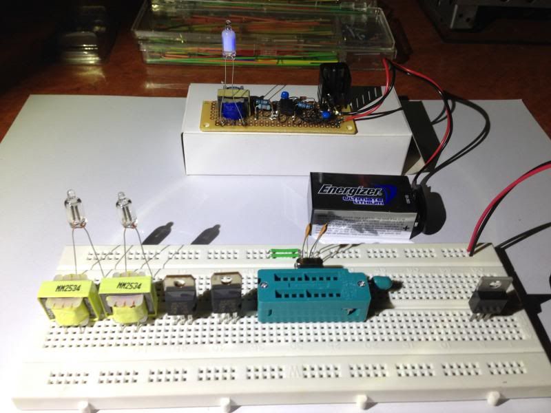
Pigtail Neons :)


Closed Thread
Results 1 to 25 of 25

Hybrid View

  1. #1
    Join Date
    Aug 2003
    Posts
    985

    Default Pigtail Neons :)

    Hi Guys,
    I did a circuit a while back... a schematic flogged off the net to drive a neon with low voltage.
    It's 555 timer controlled, to pulse power to the transformer.
    The MJE355 transistor gets very hot very quickly, and I never sorted that out.
    THe transformer itself, stays cool.


    This time I can check the impedance of the transformer primary isn't real low,
    and also I want to replace the 555 timer with a pic so I can vary the pulse width duty cycle and frequency.
    Maybe some combination will cool it down.
    Also two channels, and the potential quick fix of dimming the neon on & off in steps rather
    than leave it on constantly.
    There will be some compromise on the dimming speed to ensure it can be cool.

    Our local electronics supplier do blue, green , and original red neons now.

  2. #2
    Join Date
    Nov 2003
    Location
    Greece
    Posts
    4,115


    Did you find this post helpful? Yes | No

    Default Re: Pigtail Neons :)

    MAybe the switching of the MJE355 has slow slope and operates in linear region for long time. Have you checked with a scope?

    Ioannis

  3. #3
    Join Date
    Sep 2009
    Posts
    755


    Did you find this post helpful? Yes | No

    Default Re: Pigtail Neons :)

    I can't find datasheet for MJE355. I suppose that you meant MJE3055. I would try with logic level mosfet.
    One reason for getting to hot is slope, as Ioannis mention, but probably isn't that.
    Other:
    1) What is type of transformer core, maybe frequency is to high.
    2) Is that flyback topology? Maybe core is saturated.
    3) Maybe emitter collector breakdown occur, I don't see any clamp on collector.
    4) Neon have very low impedance when glowing, so try to put resistor in series to limit current.
    etc...

  4. #4
    Join Date
    Sep 2009
    Posts
    755


    Did you find this post helpful? Yes | No

    Default Re: Pigtail Neons :)

    Forget to mention, if is flyback then you need diode on output, if is single switch forward, then you need to "reset" core, and you must have an inductor on output.

  5. #5
    Join Date
    Oct 2012
    Posts
    82


    Did you find this post helpful? Yes | No

    Default Re: Pigtail Neons :)

    I’m not an expert in this field but few months ago I’ve been playing with non-contact power transfer.

    I agree with the points made by Ionnis and pedja089 and add few notes of my own:

    Your LC circuit and its Q factor will determine your frequency needed and your efficiency.
    For the same setup your duty cycle will change the power input / output ratio drastically.
    In your case you should draw no more than few tens of milliamps. If your outputs are getting hot you are drawing too much and inefficiently.
    I’m not sure what kind of diagnostic tools you have on your bench but an oscilloscope and a variable frequency generator will be more than helpful. Monitor the output signal from your Mosfet with the scope and change the frequency until you get maximum output level, cleanest signal shape and minimum current draw from your power source. If you don’t have an oscilloscope just by monitoring the current draw will get you close to optimum. You want to stimulate your circuit with its resonant frequency for best results. Once you got over this step start changing the duty cycle of the driving signal with the same goals in mind. As we discuss in one of the treads I started in about two months ago you can use a low caliber PIC to create your output. Dealing with low frequencies will also give you access to a wide duty cycle range.
    The shape of the signal driving your output device (try to make it as square as possible) is extremely important. The amplitude of this signal is also important. Try using TTL level Mosfets or use a Mosfet driver. The Mosfet driver made all the difference for my application and it is TTL compatible. Most of the Mosfets available have the needed diode built in.
    If you are using audio type transformers your optimum frequency should be really low.

    HTH

    Regards,

    Nick

  6. #6
    Join Date
    Oct 2012
    Posts
    82


    Did you find this post helpful? Yes | No

    Default Re: Pigtail Neons :)

    One clarification to my above reply:
    If I recall it correctly older Neons used to draw less than 1mA from about 100 - 150 V supply which makes it about 100 – 150 mW per bulb in the worst case. I think that about 100K series limiting resistors were commonly used (the value of the resistor varies with the voltage). Depending on your input voltage to the converter you should draw 25 – 35 mA from 5V and 10 – 20 mA from 12V input. The estimated current draw includes generous losses in your system.

    Regards,

    Nick

Members who have read this thread : 0

You do not have permission to view the list of names.

Posting Permissions

  • You may not post new threads
  • You may not post replies
  • You may not post attachments
  • You may not edit your posts