Code:
'
' This setup uses a PIC16F688 and a FM24V01, 128kB Nonvolatile RAM to test
' the I2CREAD/WRITE functions at 4MHz.
'
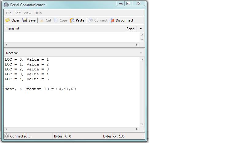
' First: The FRAM memory is loaded with values 1~5 starting from
' location 0 using Word size address. The values written are sequentially
' loaded into the next memory location, so only the starting address is
' needed for this test.
' Read address = $A0
' Write address = $A1
'
' Second: The FRAM memory locations 0 thru 4 are READ in a loop then stops
' and waits the Test button on the LAB-4X to be pushed and repeats.
'
' The data was monitored with the Saleae Logic scope.
' Max clock speed measured at 4Mhz was 29kHz
'
' The DEBUG function was used this time.
'****************************************************************
#CONFIG
ifdef PM_USED
device pic16F688, intrc_osc_noclkout, wdt_on, mclr_on, protect_off
else
__config _INTRC_OSC_NOCLKOUT & _WDT_OFF & _PWRTE_ON & _MCLRE_OFF & _CP_OFF & _CPD_OFF & _BOD_OFF & _IESO_OFF & _FCMEN_OFF
endif
#ENDCONFIG
'-----------------------------------------------------
PORTA=0
PORTC=0
TRISA = %00001000 ' All 8 bits assigned one way or the other
TRISC = %00000000 ' All 8 bits assigned one way or the other
CMCON0 = 7
ANSEL = 0
OPTION_REG = 128 ' PORTA pullups disabled
INTCON=128
OSCCON = %01100001 ' Oscillator set to 4MHz
DEFINE DEBUG_REG PORTC
DEFINE DEBUG_BIT 3
DEFINE DEBUG_BAUD 19200
DEFINE DEBUG_MODE 1
DEFINE OSC 4
Include "modedefs.bas"
'-----------------------------------------------------------
Manf VAR BYTE[3]
Value VAR BYTE
LOC VAR WORD ' FRAM address must be sent as Word size
x VAR BYTE
'------------------------------------------------------------
SCL VAR PORTA.4 ' RA4, pin #3
SDA VAR PORTA.5 ' RA5, pin #2
Change VAR PORTA.3 ' Push button on LAB-X4
LED VAR PORTA.0 ' Test LED. LOW = ON
'------------------------------------------------------------
LOC = 0 ' Start at 0
LED = 1 ' Turn LED OFF
PAUSE 1000 ' Give me a chance to start the monitor
GOSUB Load_Mem ' Load FRAM memory locations 0~4 with values 1~5
Main:
FOR LOC = 0 TO 4
LED = 0 ' Turn ON LED, scope monitored
I2CWRITE SDA,SCL,$A0,[LOC],Fail1
PAUSEUS 25 ' Paused to see on display
I2CREAD SDA,SCL,$A1,[VALUE],Fail2
DEBUG "LOC = ", DEC LOC,", ","Value = ", DEC Value,13,10
LED =1 ' Turn OFF LED
NEXT LOC
DEBUG 13,10 ' Add a space between readings
' Send Reserved Slave ID $F8 and address
I2CWRITE SDA,SCL,$F8,[$A1],Fail1
PAUSEUS 25 ' Paused to see on display
' Send Reserved Slave ID $F9 and address then read in 3 bytes
I2CREAD SDA,SCL,$F9,$A1,[Manf[0], Manf[1], Manf[2]],Fail2
' Debug Manufacture and Product ID. This FRAM = 00x41x00
DEBUG "Manf, & Product ID = ",HEX2 Manf[0],",",HEX2 Manf[1],",",_
HEX2 Manf[2],13,10,13,10
WHILE CHange: WEND ' Wait until button pushed
PAUSE 500 ' Cheap debounce
GOTO Main
'----------------------- Fail routines -------------------------------
Fail1: ' Try Write again
FOR x=0 to 50
LOW LED : PAUSE 50 : HIGH LED : PAUSE 50
Next x
GOTO Main
Fail2: ' Try read again
For x=0 to 5
LOW LED : PAUSE 250 : HIGH LED : PAUSE 250
Next x
GOTO Main
'---------------------- Load FRAM --------------------------------------
Load_Mem:
LED = 0 ' Turn ON LED, scope monitored
I2CWRITE SDA,SCL,$A0,[LOC,1,2,3,4,5],Fail1
LED = 1 ' Turn OFF LED
RETURN
END
Now the Debug at 19.2k..


Bookmarks