Yes, of course, that information is important as well. The PIC is 16F676, does not have a USART, OSC @ 4MHz, data coming at PortA.3.
I want to understand at that rate of interrupts, how is the transmission not getting messed up?
Yes, of course, that information is important as well. The PIC is 16F676, does not have a USART, OSC @ 4MHz, data coming at PortA.3.
I want to understand at that rate of interrupts, how is the transmission not getting messed up?
Can you post the code so we can see how the serial input is handled? SERIN? DEBUGIN? Some custom bit banged rotuine?
[speculating]
That ASM interrupt is pretty short and quick, I count ~14 cycles. (14us @ 4MHz) or something.
"Stealing" 14us every 784us is around 1.8% of the available processing power. Yes, context save and restore adds to that.
At 2400baud each bit is 416us, perhaps the error is small enough for it to not cause any trouble.
[/speculating]
Switching to DT-Ints with the ISR written in PBP will in this case add A LOT of cycles to the interrupt processing due the overhead of saving and restoring all the PBP system variables.
/Henrik.
When in doubt, measure - so I did.
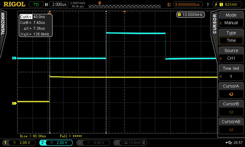
Here's the testcode I used:I'm feeding pulses into PortB.0 which trips an interrupt. The interrupt routine sets PortB.7 high so the time between the rising edge of input and output is the interrupt latency. I captured the result with the scope:Code:INCLUDE "DT_INTS-18.bas" INCLUDE "ReEnterPBP-18.bas" ASM INT_LIST macro ; IntSource, Label, Type, ResetFlag? INT_Handler INT0_INT, _TimezUp, PBP, yes endm INT_CREATE ; Creates the interrupt processor ENDASM @ INT_ENABLE INT0_INT ; enable Timer 1 interrupts TRISB = %00000001 'PortB.0 input Main: PortB.7 = 0 ' Turn off output Goto Main TimezUp: PortB.7 = 1 @ INT_RETURN
The bottom trace is the inout signal triggering the interrupt, the upper trace is output of PortB.7.
The time difference is ~7.4us which is around 120 cycles since my PIC is running at 64MHz. Then you'll have an equal amount of time to restore all the variables when returning from the interrupt which the width of the pulse in the upper trace shows.
/Henrik.
Thanks Henrik. This explains a lot. I do not have an any device currently with me so I could not measure it at the moment.
Few things come to mind - What is the actual acceptable delay/error @ 2400 baud? Is it upto 20uS - 40uS that the transmission will not be affected? This would help, as I may use an higher oscillator, lets say 20MHz and bring down the latency if possible. Secondly, DT_INT also has assembly routine type interrupts, could you please check those for me, what is the latency there. If the way exists and all fits in, I would like to make this work using DT INT only without adding another PIC to handle the RF part.
Hi,
Simply changing the interrupt declaration from type PBP to ASM makes the latency go from 7.4us to 2.7us (around 40 cycles) with the code in my previous post.
However, if you're going to use assembly interrupts I don't really see the need for DT-Ints. You can not use PBP statements in an interrupt routine declared as ASM (well it IS possible but it's very easy to screw things up and really not recommended).
I don't know what an acceptable error at 2400baud is OR how the bitbanged serial routines in PBP works when being interrupted like that. Apparently it does seem to work the way you currently have it. I guess one way for you to find out is to try.
/Henrik.
Bookmarks