Shiftout data needs to be sent on rising edge of clock


Closed Thread
Results 1 to 10 of 10
  1. #1
    Join Date
    Feb 2012
    Posts
    64

    Default Shiftout data needs to be sent on rising edge of clock

    I have a chip that needs to read SPI data on the rising edge of the clock. The shiftout command seems to always send the data on the falling edge and I can't find any settings to change that. The Shiftin command allows for read either before or after sending the clock signal. Any Suggestions?

    Jim

  2. #2
    Join Date
    Oct 2005
    Location
    Sweden
    Posts
    3,569


    Did you find this post helpful? Yes | No

    Default Re: Shiftout data needs to be sent on rising edge of clock

    Hi Jim,
    According to the manual both MODE 0 (LSBFIRST) and 1 (MSBFIRST) idles the clock LOW.
    For Modes 0-1, the clock idles low, toggles high to clock in a bit, and then returns low. For Modes 4-5, the clock idles high, toggles low to clock in a bit, and then returns high.
    Are you saying that, when using either MODE 0 or 1, the databit isn't true on the rising edge?

    /Henrik.

  3. #3
    Join Date
    Feb 2012
    Posts
    64


    Did you find this post helpful? Yes | No

    Default Re: Shiftout data needs to be sent on rising edge of clock

    Henrik,
    Yes, on Mode 1 the databit is just starting to climb. Any bit following a zero doesn't register, but if two bits in a row are sent the second one will register since the data stays high.

    I am using Mode 1 (MSB first, Clock idles low). The clock should be low when not in use so I never tried mode 5. The chip I am trying to control echos the data back that it received. When hooked up to a scope I can see the data being sent is on the falling edge and the data I read back from the chip shows a weak signal where it should show high (similar to the rising edge data just starting to climb).

    Shiftin seems to have more options.
    Thanks,

    Jim


    The shiftin command has an option to read either before or after sending the clock (Which to me sounds more like the rising or falling edge).

  4. #4
    Join Date
    Oct 2005
    Location
    Sweden
    Posts
    3,569


    Did you find this post helpful? Yes | No

    Default Re: Shiftout data needs to be sent on rising edge of clock

    Hi Jim,
    I just tried it here, 18F25K20 running at 64MHz.
    Code:
    TRISC = %10000000                       ' 
    TRISB = %00000000                       ' 
    
    Datapin var PortB.7    ;
    Clockpin var PortB.6   ;
    CS var PortB.5
    
    PortB = %00100000       ' Setup initial pin states.
    Pause 100
    
    Start:
      CS = 0
      shiftout Datapin, Clockpin, 1, [%10001000]
      CS = 1
      Pause 100
    Goto Start
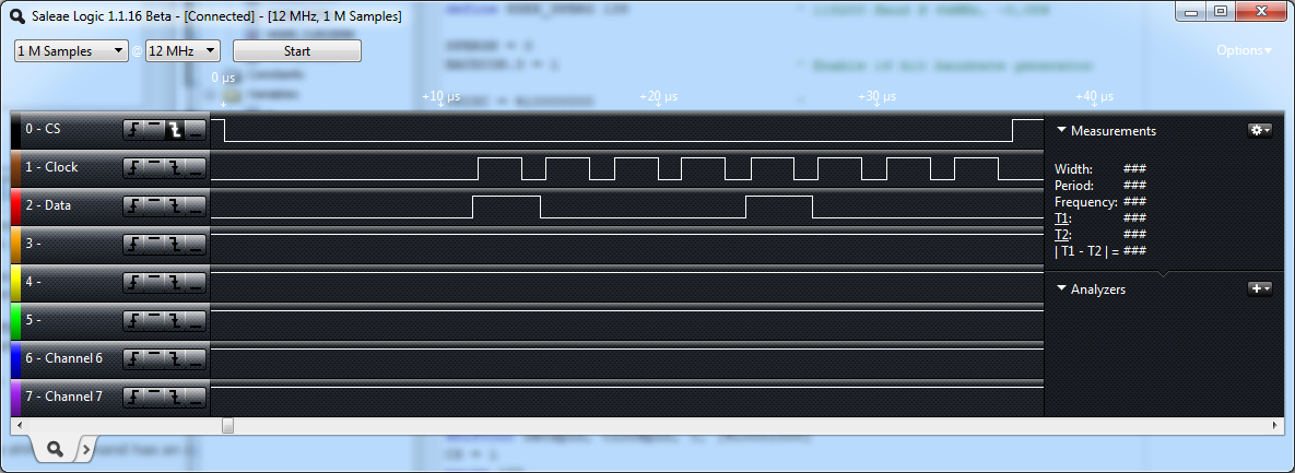
    As you can see I'm using MODE 1 (clock idles low, MSB first). I captured the result with my logic analyzer:
    Name:  Shiftout.png
Views: 1323
Size:  98.7 KB

    As you can see the datapin is indeed true before the rising edge of the clock, throwing some markers on it tells me that the datapin goes true 250nS before the rising edge of the clock signal but that will be different depending on the oscillator speed.

    Do you have anything else on your data output pin (like a LED or, worse, something capacitive) that can possible load output driver making its risetime increase?

    /Henrik.

  5. #5
    Join Date
    Feb 2012
    Posts
    64


    Did you find this post helpful? Yes | No

    Default Re: Shiftout data needs to be sent on rising edge of clock

    Henrik,
    Thanks for helping me with this. I don't know why my setup is showing the data slightly after the rising edge. I am using a similar micro (18f26k22), only I am using the internal Osc at 16MHz. Your output shows that the data should be good on both the rising and falling edge.

    Each SPI line I am using has a 3.9k resistor between the PIC's I/O and the device, but nothing else. (I have a resistor on the Clock, CS, DO, and DI signals)

    I like your logic output. I am using a pickit2 to load the hex file and program the Pic. I am wondering if I am missing out on some decent tools by not using MPLab.

  6. #6
    Join Date
    Oct 2005
    Location
    Sweden
    Posts
    3,569


    Did you find this post helpful? Yes | No

    Default Re: Shiftout data needs to be sent on rising edge of clock

    Hi Jim,
    At 16Mhz you should have even more delay between the datapin going "true" and the rising edge of the clock - have you verified that it's actually running at 16MHz? (Can't see how that would actually make the data go true after the clock but anyway...)

    When capturing the output with your scope, are you measuring on the PIC pins?
    Are the PIC and the other chip both running off the same supply or are you doing some kind of level conversion with the 3.9k resistors?

    Try disconnecting one side of the resistor and measure again to verify that the PIC is actually setting the states correctly.

    I don't use MPLAB myself and the only thing I know I'm missing is source level debugging. As for the logic analyzer it's the Saleae LOGIC (8 channel version) - it's absolutely great for the money, worth every cent.

    /Henrik.

  7. #7
    Join Date
    Feb 2012
    Posts
    64


    Did you find this post helpful? Yes | No

    Default Re: Shiftout data needs to be sent on rising edge of clock

    Henrik,
    I had the scope connected after the 3.9k resistors. I have the resistors connected directly to the PIC pins for protection and then I run wires (About 6" to a connector which goes directly to the IC I am sending data to). The scope probes were clipped to the wires at the connector end. There is no level conversion going on however, the chip I am sending the SPI commands to is powered by a different source. The grounds are tied together. Everything runs at 3.3V

    I will get someone to help me measure the signals directly at the PIC pins with nothing else attached and I will let you know if it looks any better.

    Thanks for your help,

    Jim

  8. #8
    Join Date
    Feb 2012
    Posts
    64


    Did you find this post helpful? Yes | No

    Default Re: Shiftout data needs to be sent on rising edge of clock

    Henrik,
    I tested the signals again on the scope at the PIC pins and although the data signal is well over the falling edge it is also over the rising edge, so the SPI should be working. I will need to experiment a bit with the cable length/sheilding, etc.

    I did want to let you know that I ordered the Saleae Logic Analizer you told me about. I was having a difficult time deciding on the 8 channel or 16 channel, but eventually decided that the 8 channel would serve me o.k. The analyzer should help all future projects, so you were already a big help.

    Thanks,

    Jim


    Quote Originally Posted by HenrikOlsson View Post
    Hi Jim,
    At 16Mhz you should have even more delay between the datapin going "true" and the rising edge of the clock - have you verified that it's actually running at 16MHz? (Can't see how that would actually make the data go true after the clock but anyway...)

    When capturing the output with your scope, are you measuring on the PIC pins?
    Are the PIC and the other chip both running off the same supply or are you doing some kind of level conversion with the 3.9k resistors?

    Try disconnecting one side of the resistor and measure again to verify that the PIC is actually setting the states correctly.

    I don't use MPLAB myself and the only thing I know I'm missing is source level debugging. As for the logic analyzer it's the Saleae LOGIC (8 channel version) - it's absolutely great for the money, worth every cent.

    /Henrik.

  9. #9
    Join Date
    Oct 2005
    Location
    Sweden
    Posts
    3,569


    Did you find this post helpful? Yes | No

    Default Re: Shiftout data needs to be sent on rising edge of clock

    Hi Jim,
    You won't be dissapointed with your LOGIC!
    It does sound like the PIC outputs are driving something capacitive. You mention a cable which obviously is capacitive to some extent. However, since the clock and data both are transmitted thru the same cable (I assume) one would think that the loading/delay on the clock would be equal to that on the data-line thus making no practical difference.

    Please let us know how it works out.

    /Henrik.

  10. #10
    Join Date
    Feb 2012
    Posts
    64


    Did you find this post helpful? Yes | No

    Default Re: Shiftout data needs to be sent on rising edge of clock

    Henrik,
    I am happy with the Logic. At first when I opened the case I thought they forgot to package the device until I realized how small it is! Very nice device. I was only able to sample between 8MHz-12MHz for some reason, but for anayzing the SPI it was a nice clean signal. Being able to see the data sent/received in Hex was a nice bonus feature. The chip I am trying to control seems to be the problem rather than what I am sending. I am going to try looking at the hardware SPI on the PIC instead to see if it makes a difference.


    Quote Originally Posted by HenrikOlsson View Post
    Hi Jim,
    You won't be dissapointed with your LOGIC!
    It does sound like the PIC outputs are driving something capacitive. You mention a cable which obviously is capacitive to some extent. However, since the clock and data both are transmitted thru the same cable (I assume) one would think that the loading/delay on the clock would be equal to that on the data-line thus making no practical difference.

    Please let us know how it works out.

    /Henrik.

Similar Threads

  1. reducing shiftout clock freq and PS2/PC interfacing ....
    By wireless magic in forum mel PIC BASIC Pro
    Replies: 18
    Last Post: - 26th February 2008, 21:15
  2. After Shiftout where is the clock signal???
    By makson in forum mel PIC BASIC Pro
    Replies: 0
    Last Post: - 31st August 2007, 19:27
  3. SHIFTOUT Clock rate
    By Brock in forum mel PIC BASIC Pro
    Replies: 10
    Last Post: - 9th July 2006, 00:42
  4. Best way to find a rising edge?
    By jcsquire in forum mel PIC BASIC Pro
    Replies: 4
    Last Post: - 31st May 2006, 16:11
  5. Replies: 2
    Last Post: - 5th June 2005, 20:55

Members who have read this thread : 0

You do not have permission to view the list of names.

Tags for this Thread

Posting Permissions

  • You may not post new threads
  • You may not post replies
  • You may not post attachments
  • You may not edit your posts