Hi Everyone,
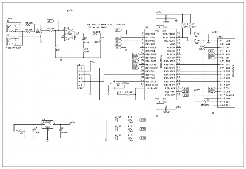
I join here looking for ideas and help on a project that I am trying to build. What I want to have the main system which I am showing here with the schematic. I want to have a 3x4 keypad for the user to input values. What I came across is that all the pins on that schematic are being used. So the question of using two pics came across, one as a slave and one as a master. But I have no idea how the wiring/ connection are going to be. Once I figure that out I will look into the coding next.
This is the 3x4 device, http://www.pcreview.co.uk/forums/3x4...-t3043773.html
I am using a PIC18F4550, http://ww1.microchip.com/downloads/e...doc/39632c.pdf


Bookmarks