Hi,
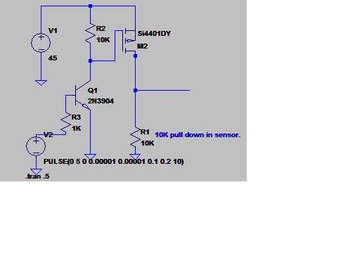
Thank you for posting the schematic Ioannis, that's the circuit I tried to describe earlier.
Looking at the datasheet for the P-channel MOSFET we can see that it has a specified gate threshold of -2 to -4V (ie it starts to conduct at a Vgs of -2 to -4V) and a maximum Vgs of +/-20V. In this case simply grounding the gate of the P-channel thru the N-channel switch would have put 24V between the gate and the source of the P-channel MOSFET which is out of spec for it - the voltage divider takes care of that.
When the N-channel MOSFET is "off" the gate of the P-channel is pulled up to 24V by the 1k resistor, the P-channel MOSFET is off. When the N-channel MOSFET turns on it grounds the lower side of the voltage divider which makes the voltage at the gate of the P-channel MOSFET ~7.5V. 7.5V at the gate minus 24V at the source gives a Vgs of -16V which is well above the threshold yet within the +/-20V maximum.
Obviosuly, using a 74A MOSFET to switch 100mA is overkill but the principle of switching the high side is the still same. Using a solid state relay as suggested or perhaps even an optoisolator capable of supplying the current would of course work nicely too.
/Henrik.


 Re: Fet for turning on high voltage.
 Re: Fet for turning on high voltage.


Bookmarks