Reading sensors with 3.3v(beginner)


Closed Thread
Results 1 to 18 of 18

Hybrid View

  1. #1
    Join Date
    Nov 2003
    Location
    Wellton, U.S.A.
    Posts
    5,924


    Did you find this post helpful? Yes | No

    Default Re: Reading sensors with 3.3v(beginner)

    I am going to suggest writing a test code with that only reads the ADC in a loop with a serial output to the terminal. No interrupts.
    Code:
    TestLoop:
     TOGGLE StatusLed1  ' faster process
     ADCIN 0, ambval
      '-------------
     ADCIN 1, batval
         '-------------
     ADCIN 2, axval
     ADCIN 3, ayval
     ADCIN 5, azval
     hserout ["Light ", DEC ambval," Bat ", Dec batval, " X: ",Dec axval," Y: ",Dec ayval," Z: ",Dec azval, 13] ' just to see it on the hyperterminal
     PAUSE 250
     GOTO TestLoop
    I see in your code a couple of things that might be causing an issue.

    @ INT_RETURN Remove this.


    error:
    Toggle led
    @ INT_RETURN
    And the TMR1 interrupt may not be long enough time wise for everything to happen that you have in it. The test code if it works will help track down the problem.

    Maybe someone else sees what I am missing though.
    Dave
    Always wear safety glasses while programming.

  2. #2
    Join Date
    Jun 2011
    Location
    Philippines
    Posts
    223


    Did you find this post helpful? Yes | No

    Default Re: Reading sensors with 3.3v(beginner)

    Hi Dave, thanks for helping me out, I did what you suggested unfortunately the same result...I will try to change some pin assignment and see if it will help.

    kind regards,
    tacbanon

  3. #3
    Join Date
    Jun 2011
    Location
    Philippines
    Posts
    223


    Did you find this post helpful? Yes | No

    Default Acceleromter module test(3.3v) + Pic16F887 (5v)

    Hi, I did some testing but this time using PIC16F887 on 5v just to isolate the specific program which is to read the accelerometer module on 3.3v..using the following code.
    Code:
    '' Program Start Here ''
    
    DEFINE osc 20           ' We're using a 4 MHz oscillator
    DEFINE ADC_BITS 8       ' Set A/D for 8-bit operation
    DEFINE ADC_CLOCK 3      ' Set A/D clock Fosc/8
    DEFINE ADC_SAMPLEUS 50  ' Set A/D sampling time @ 50 uS
    
    ANSEL = %11111111 ' Make AN0-AN7 Analog
    ANSELH= %00000000 ' Make AN8-AN13 digital
    
    accx var byte
    accy var byte
    accz var byte
    
    DataOut var Byte
    DataOut = 0
    
    '    PORT setting
        '    ============
             '
              TRISA = %11111111   ' Set PORTA to all input
              ADCON1 = %0001001  ' Set PORTA.0,1,2,4,5,6 = A/D, PortA.3 = +Vref
              TRISC = %10000000        ' RC.7 => USART RX pin set to input
                                    ' all other pin set to output
             'OPTION_REG = $7f       ' Enable PORTB pull-ups
                                    '
             TRISB=%00000000                ' RB<7:0> set to output
             TRISD=%00000000
             
    '    USART setting
        '    =============
             ' Since we will not use HSERIN/HSEROUT, we must
             ' write directly to internal PIC register
             ' 
             TXSTA=$24              ' enable transmit and SPBRGH=1
             RCSTA=$90              ' Enable USART and continuous receive
             SPBRG=129          ' BAUD RATE = 9600 BAUDS
    
    '    Interrupt definition
        '    ====================
             '
             PIE1.5   =1            ' enable USART receive interrupt
             INTCON.6 =1            ' enable peripheral interrupt
        
        '    Alias definition
        '    ================
             '
             RCIF       var PIR1.5   ' receiver interrupt
             UserLED1   var PORTB.0  ' the LED who show a 'running process'
             UserLED2   var PORTB.1  ' the LED1 that user want to control
             UserLED3   var PORTB.2  ' the LED2 that user want to control
            
             
        '    Variable definition
        '    ===================
             '
             Delay     var word     ' 
             DataIn    var byte     ' use to store RCREG content
             Discard   var byte     ' use to erase RCREG register
            
        '    Hardware/software initialisation
        '    ================================                                                                                                                                                         
             '
             PORTB=0                ' clear PORTB   
             PORTC=0                ' dlear PORTC      
             on interrupt goto USARTInterrupt


        PAUSE 500           ' Wait .5 second
    
    loop1:
        ADCIN 0, accx: ADCIN 1, accy: ADCIN 2, accz
        Hserout["Data receive: X:",Dec accx," Y:",Dec accy," Z:" ,Dec accz, 13] 
        Pause 200
       
        GOTO loop1               ' Do it forever
    
        END
        
    disable interrupt
    USARTInterrupt:
        '    Here's the interrupt routine who will make the user
        '    much happy by giving him the feeling to have the 
        '    control on the machine when the status of the user
        '    LED will change
        '
        RCSTA=0                     ' Disable serial port AND
                                    ' clear possible error (FERR,OERR)
                                    
        datain=RCREG                ' Get data
                                    
        while RCif                  ' wait untill the RCREG is empty
              discard=RCREG         ' by reading it and store result in a
        wend                        ' don't care variable
                                    
        select case datain          ' What to do with that data???
                                    
               case "1"            ' User selection = 1
                    userled1=1       '      => Enable the LED
                                    
               case "2"           ' User selection =2
                    userled1=0       '      => disable the LED
               
               case "3"           ' User selection =2
                    userled2=1       '      => disable the LED
                    
               case "4"           ' User selection =2
                    userled2=0       '      => disable the LED
                    
               case "5"           ' User selection =2
                    userled3=1       '      => disable the LED
                    
               case "6"           ' User selection =2
                    userled3=0       '      => disable the LED
                    
               case "a"           ' User selection =2
                    PortB=%00000111       '      => disable the LED
               case "d"           ' User selection =2
                    PortB=%00000000       '      => disable the LED   


               end select           
        RCSTA=$90                   ' Re-enable the serial PORT AND
        resume                      ' get out of here
    enable interrupt
    I have the following reading:

    Name:  Accel_test2.png
Views: 1097
Size:  6.9 KB
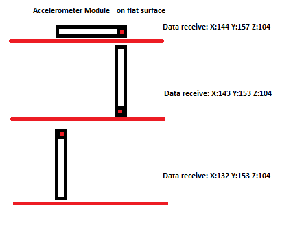
    and I think I'm not getting the right output...what might causing it?

    Kind regards,
    tacbanon

  4. #4
    Join Date
    Jun 2011
    Location
    Philippines
    Posts
    223


    Did you find this post helpful? Yes | No

    Default Re: Acceleromter module test(3.3v) + Pic16F887 (5v)

    Hi all, I'm gonna try to use an i2c accelerometer but from where I'm located (province) it will take some days to arrive...then post here my inquiries .
    I'm gonna try to move on to another sensor(barometric) while waiting for the accelerometer.

    Regards,
    tacbanon

  5. #5
    Join Date
    Mar 2011
    Location
    Los Angeles, California
    Posts
    322


    Did you find this post helpful? Yes | No

    Default Re: Acceleromter module test(3.3v) + Pic16F887 (5v)

    Hi Tacbanon!
    I would be very interested in your results with your accelerometer as I am in need of a tilt sensor (pitch and roll). I see you are looking for a barometric sensor and you may wish to look at http://www.picbasic.co.uk/forum/showthread.php?t=16457 which is a depth sensor which should work for altitude as well. If nothing else there is a 3.3v to 5.0v level converter that may be useful for your project.

    Best, Ed

  6. #6
    Join Date
    Jun 2011
    Location
    Philippines
    Posts
    223


    Did you find this post helpful? Yes | No

    Default Re: Acceleromter module test(3.3v) + Pic16F887 (5v)

    Greetings Ramius!
    Thanks for your interest, and very thankful for the guide, and I will try this(3.3v to 5.0 converter).

    regards,
    tacbanon

Members who have read this thread : 0

You do not have permission to view the list of names.

Posting Permissions

  • You may not post new threads
  • You may not post replies
  • You may not post attachments
  • You may not edit your posts