work flow- how to move from one MCU to another


Closed Thread
Results 1 to 6 of 6
  1. #1
    Join Date
    Jun 2011
    Location
    Indian Harbour Nova Scotia
    Posts
    108

    Default work flow- how to move from one MCU to another

    I wrote some code to control two linear actuators, using my Lab X1 development kit with 16F887 MCU on board.

    I made a PCB with the intention of using a 16F628 MCU and now I have to switch from one to the other, ie to get my code into the 16F628.

    The changes in code are not difficult, in fact I used the same pins on both, but I want to know what I should do next.

    My idea is to use the Lab x1 with appropriate jumpers to the 16F628 MCU SOCKET on my PCB to test the code in real time. There are only a few wires, so not a problem. I made the PCB so that I could access the 4 connections required for programming the 16F628. After my testing is complete and I plug my 16F628 into its socket, is this what I do:
    • Make the necessary software changes for the new chip.
    • Hook up the U2 programmer to the 16F628 MCU, compile, and program?
    What about debugging? Will I ever be able to use the MicroCode Studio debugger since I don't have access (USB) like I do on the LabX1?

    Please feel free to poke holes in my logic. Thanks

  2. #2
    Join Date
    Jan 2005
    Location
    Montreal, Quebec, Canada
    Posts
    2,820


    Did you find this post helpful? Yes | No

    Default Re: work flow- how to move from one MCU to another

    Make sure your code fits on the 16F628.

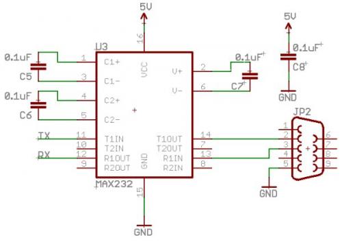
    I also have the Lab-X1 and U2 USB programmer. This is what I use for in-circuit debugging:
    http://www.sparkfun.com/tutorials/104


    Robert

  3. #3
    Join Date
    Jun 2011
    Location
    Indian Harbour Nova Scotia
    Posts
    108


    Did you find this post helpful? Yes | No

    Default Re: work flow- how to move from one MCU to another

    Thanks for this. I went to the Sparkfun address but didn't find the info I wanted regarding the schematic you posted. RX and Tx connect to ? Is there any software that goes with it or do I just use the Microcode Studio debugger as usual? The Lab X1 uses this chip and a 75176 IC as well. Is that needed? (looks like it's only there for 485 comm).

    Bob

  4. #4
    Join Date
    Jan 2005
    Location
    Montreal, Quebec, Canada
    Posts
    2,820


    Did you find this post helpful? Yes | No

    Default Re: work flow- how to move from one MCU to another

    Quote Originally Posted by queenidog View Post
    ... RX and Tx connect to ? ...
    The RX and TX pins on your PIC (C6 and C7), refer to the datasheet. The Lab X1 is wired for this already.


    Quote Originally Posted by queenidog View Post
    ... Is there any software that goes with it or do I just use the Microcode Studio debugger as usual? ...
    That's what I use.


    Quote Originally Posted by queenidog View Post
    ... The Lab X1 uses this chip and a 75176 IC as well. Is that needed? (looks like it's only there for 485 comm)...
    I look at the schematic for the Lab X1 and can't come up with a reason why it wouldn't work. I had made that circuit way back when I started with a U2 serial programmer; didn't have the Lab X1 then.

    I probably just got in the habit of using my old thing-a-ma-bob.

    I don't know the 75176 chip but it isn't connected to the RS485 connector for nothing. I'm guessing JP4 comes into play (this is only conjecture at this point). I haven't had to check RS232 on the Lab X1 yet.

    Robert

    From LabX1.txt:
    RS232
    ... PORTC.6 and PORTC.7 are shared with the RS485 driver. Only one of the two
    interfaces, RS232 or RS485, should be installed at a time.
    ...
    RS485
    ...To enable RS485 communications, remove the MAX232 from its socket and install an RS485 driver IC. Pin compatible ICs include the MAX485 and SN75176, among others....JP4 controls the receive enable (/RE) line. This line is normally grounded to allow the received data to always appear on PORTC.7....
    I don't have an SN75176 on my Lab X1. So unless you put one in, you should be set to go (my programming PC is not available right now)
    Last edited by Demon; - 5th March 2012 at 02:21.

  5. #5
    Join Date
    Jun 2011
    Location
    Indian Harbour Nova Scotia
    Posts
    108


    Did you find this post helpful? Yes | No

    Default Re: work flow- how to move from one MCU to another

    Thanks Robert, this is really helpful.
    Now that I look at the LabX1 schematic, I'm thinking I don't even have to make this little circuit which I could whip up quickly. I should be able to grab the two signals (Tx and Rx) right off the LabX1 board, at least where the LabX1 is close to my project.

    Another question: Is there a USB version for this? The LabX1 has serial input and your schematic shows a DB9 which I assume is serial interface as well. Pretty well none of my new computers have serial or parallel connections anymore, in fact I had to buy a serial PCI card for my computer just to run the debugger.

  6. #6
    Join Date
    Jan 2005
    Location
    Montreal, Quebec, Canada
    Posts
    2,820


    Did you find this post helpful? Yes | No

    Default Re: work flow- how to move from one MCU to another

    MeLabs has adapters here (thanks to Bruce for finding this link in another thread):
    http://store.melabs.com/prod/adapters/ICD210A.html

    But then you have to get one of their ICD programmers to do the USB interfacing; that makes our USB U2 programmer obsolete. I don't know if this will work with MCS+, it only talks about MPLAB.

    As far as I know, our USB U2 programmer doesn't do in-circuit debugging (couldn't find any reference last time I checked).

    Robert

    EDIT: I do remember reading of USB-serial adapters, just never looked them up.

Members who have read this thread : 0

You do not have permission to view the list of names.

Tags for this Thread

Posting Permissions

  • You may not post new threads
  • You may not post replies
  • You may not post attachments
  • You may not edit your posts