

Hi!
I made my own tacho-volt-therometer with about the same schematic:
http://www.vandi.ro/electronics/turo...metru_auto.htm
This page is in Romanian language but maybe you and others found it useful.


Hi!
I made my own tacho-volt-therometer with about the same schematic:
http://www.vandi.ro/electronics/turo...metru_auto.htm
This page is in Romanian language but maybe you and others found it useful.
Last edited by luxornet; - 18th November 2011 at 13:05.

Thank You for link ; but with (almost) similar hardware as Yours, my schematic work fine. BUT ... I intend to use another configuration for LCD pins (for optimised PCB), based on "LCD_Any_pin" ! This is my problem !
I check many variants for these :
without results...Code:LCD_Lines CON 2 ' changed on 1, of course !!! LCD_DATAUS CON 50 ' Data delay time in us -- changed to 200 LCD_COMMANDUS CON 2500 ' Command delay time in us -- changed to 5000
Maybe the .dsn file help to understand...

fratello,
Can you post your code.
I don't get the error with your .DSN file using this code...
Code:define OSC 4 TRISA= %00010000 TRISC= %10110000 ' CMCON0 = %00000111 'Disable analog comparators. DEFINE ADC_BITS 10 ' 10 bit A/D Conversion DEFINE ADC_CLOCK 3 DEFINE ADC_SAMPLEUS 50 ' 50 uS A/D sample time VRCON = %00000000 ' Disable Comparator Voltage Reference ANSEL = %10000000 ' Set pin (AN7) to analog input, the rest to digital ADCON0 = %10011101 ' Set up A/D converter - Right Just., VDD REF., CH 7, ON ADCON1 = %00110000 ' Set up A/D Converter clock source to internal RC ' ;----[ Change these to match your LCD ]--------------------------------------- LCD_DB4 VAR PORTA.2 LCD_DB5 VAR PORTC.0 LCD_DB6 VAR PORTC.1 LCD_DB7 VAR PORTC.2 LCD_RS VAR PORTA.0 LCD_E VAR PORTA.1 LCD_Lines CON 2 ' # of Lines on LCD, 1 or 2 (Note: use 2 for 4 lines) LCD_DATAUS CON 50 ' Data delay time in us LCD_COMMANDUS CON 2500 ' Command delay time in us INCLUDE "LCD_AnyPin.pbp" ' X VAR WORD ' Main: X = X + 1 LCDOUT $FE,$80,DEC X," " GOTO Main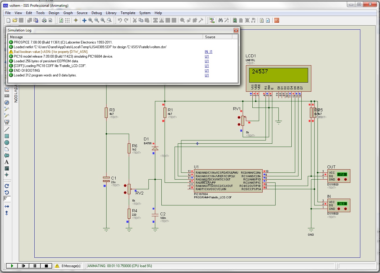
DT
Mr.Darrel ! THANK YOU for watching my post ! It's such a nice surprise !
The rest of code it's in post #1 ; just the parts concerning 16F684 and "LCD_AnyPin" it's changed...
I don't get any errors with the code from post#1.
Well, at least not with the LCD.
I think you still have some problems in the code working with the DS18B20 though.
DT
It's strange ! Using hardware and code from post #1 (and #2) the things are OK, in Proteus and "in vivo" ; changing just the configuration of LCD pins the schematic dont work anymore...I will try to build the schematic and see what happens
 Members who have read this thread : 0
You do not have permission to view the list of names.
 Posting Permissions
Bookmarks