


The attached partial schematic shows how I have Or'd the Vcc power supply with the output of a backup CR2032 lithium battery as the power source to a DS1337 real-time-clock. I did this so that when power is shut down to the microcontroller circuit, the backup battery keeps the clock running and alive, but when Vcc is on the lifetiime of the battery is perpetuated. I expected this to allow the backup battery to last for a very, very long time. Instead my lithium battery died in only a couple of weeks when by theory the DS1337 consumption should have let it last for months.
Can anyone look at this schematic and tell me why this happened and how I should change the schematic to preserve the backup battery lifetime??[IMG][/IMG]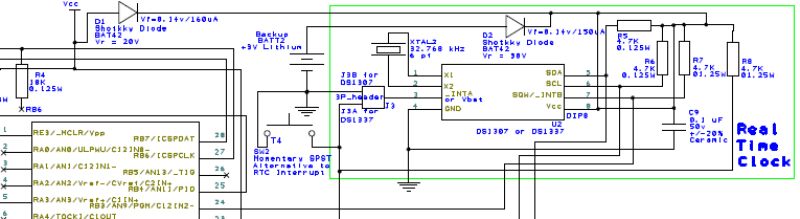


Bookmarks