

I meant WizFi210.
I will look at incorporating support for their WIZ812MJ on the same shield as the WizFi210. It will be either/or as the WizFi210 is SMD and once installed you cannot "unplug" it and plug-in the WIZ812MJ.


I meant WizFi210.
I will look at incorporating support for their WIZ812MJ on the same shield as the WizFi210. It will be either/or as the WizFi210 is SMD and once installed you cannot "unplug" it and plug-in the WIZ812MJ.
I misread the Wiz812MJ datasheet - it's SPI or parallel - not serial. Their only ethernet-to-serial TTL seems to be the Wiz105SR and it may not be possible to mount to a shield designed for the WizFi210.
OK, the Wiz105SR just barely fits on a shield PCB with enough room left over to squeeze in a 2x6 header that can connect to the module via a ribbon cable. So, while I'm still waiting on answers to a couple of questions, I'm fairly sure I'll design a shield for the Wiz105SR and the WizFi210. Both are among the least expensive modules of these types.
Dave,
the WIFI210 data sheet says UART input, Shoud it be soldered to some kind of connector pins so it can be removed or replaced ? Mabye the different modules could fit the same connectors so a choice of boards could be used, like wifi, ethernet, bluetooth etc.
Don
PICs and other µCs have UARTs - that's not the same as line drivers or transceivers. Fig. 9 in the WizFi210 manual makes it clear that it has 0-3V levels. The US dealer for WizNet checked the output of the Wiz105SR - it's 0-3V so it will need level conversion which can be as simple as a Schottky diode and pullup resistor (which will also work with a 3.3V supply). See this drawing which shows another (part of a) shield I'm working on that has six such level converters ...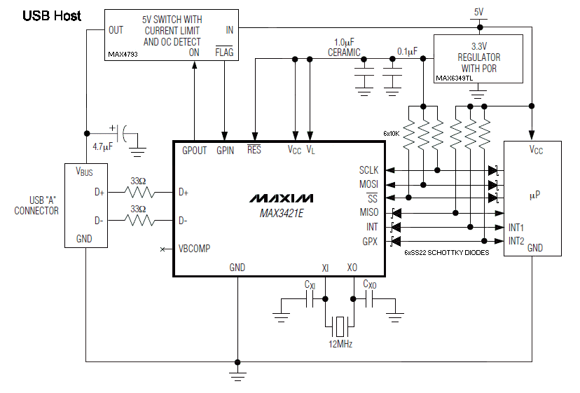
 Members who have read this thread : 0
You do not have permission to view the list of names.
 Posting Permissions

Bookmarks