I'm looking at 4 inputs though. Two for a positive trigger and two for a negative trigger.
My thought was to pull the positive ones low and the negative ones high to give a distinct change.
I'm looking at 4 inputs though. Two for a positive trigger and two for a negative trigger.
My thought was to pull the positive ones low and the negative ones high to give a distinct change.
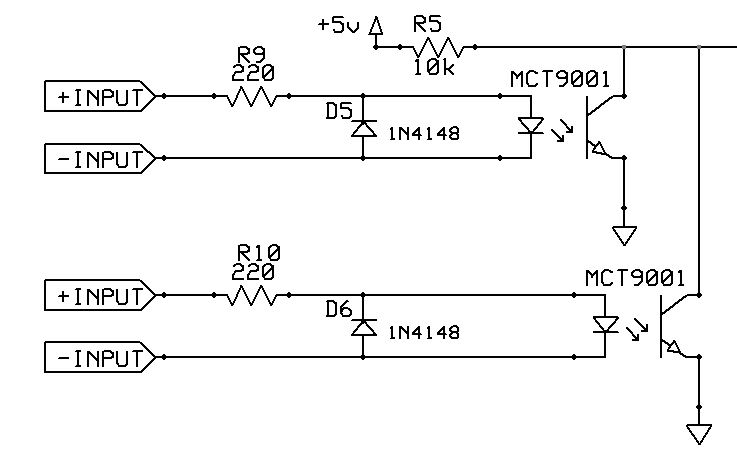
Here are two circuits I've put together. One is a voltage divider and the other is an optocoupler setup. The positive inputs on the VD setup has a cap and zener for debouncing and has pulldown resistors. The negative inputs have a pullup resistor. The VD setup allows for only one input to trigger a new routine. The opto setup requires the LED circuit to be completed in order to trigger a new routine, so the setup has to work as a pair instead of individually.
In this case, is the VD setup the better setup to use? Disregard the resistor values and they were just thrown in there.
Thanks,
Tony

Charles,
Good point about clamp ability in pins (a few pins don't have that clamp diode), but why are you using such low val resisters ? Voltage dividers with 50, 100-200K value resisters make any voltage/power dissipation insignificant. I tried a touch sensor to a/d pin through a 10 MEG ohm R (and diode) which instantly brought a/d val to full, (5 volt).
Don
Bookmarks