You can just feed the 12V into a small, 78L05-type regulator, and the output to the PIC.
You can just feed the 12V into a small, 78L05-type regulator, and the output to the PIC.
Charles Linquist
I'm looking at 4 inputs though. Two for a positive trigger and two for a negative trigger.
My thought was to pull the positive ones low and the negative ones high to give a distinct change.
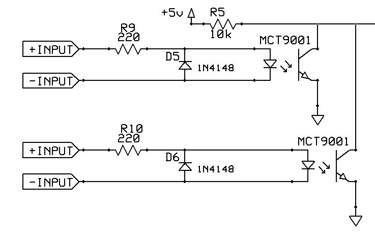
Here are two circuits I've put together. One is a voltage divider and the other is an optocoupler setup. The positive inputs on the VD setup has a cap and zener for debouncing and has pulldown resistors. The negative inputs have a pullup resistor. The VD setup allows for only one input to trigger a new routine. The opto setup requires the LED circuit to be completed in order to trigger a new routine, so the setup has to work as a pair instead of individually.
In this case, is the VD setup the better setup to use? Disregard the resistor values and they were just thrown in there.
Thanks,
Tony

Charles,
Good point about clamp ability in pins (a few pins don't have that clamp diode), but why are you using such low val resisters ? Voltage dividers with 50, 100-200K value resisters make any voltage/power dissipation insignificant. I tried a touch sensor to a/d pin through a 10 MEG ohm R (and diode) which instantly brought a/d val to full, (5 volt).
Don
Hi Guys,
Yes, I know what Charles is saying. What I'm asking though is another thing. This will be a production item, so adding a 7805 and caps to every board increases the board size and cost. My diagram from above I thought was pretty straight forward. Does it seem plausible? I think the diodes may be redundant.
Thanks,
Tony
The only comment I can make is "do you have experience with automotive electrical systems?"
Newer cars might be different, but the voltage used to vary a lot. I'd just make sure to have a circuit that can withstand up to 25V without breaking a sweat.
Oh yeah, I read a while back about some manufacturers wanting to use 24V and up, just a thought.
As for your circuit VS Charles divider or any other design, I'm not qualified to comment.
Robert
Actually, I am very familiar with vehicle systems, voltage ranges and the spikes that can occur. However, when studying how other manufacturers have created their product to be installed in such a vehicle using the same features, I don't see much protection being used. Probably because the cost of the board and the likelihood of the malfunction and repair is not cost prohibitive. It almost seems like the opto circuit would be best in isolating one circuit from the other and maybe a 12 volt zener across the LED terminals would prevent damage to the opto. Any thoughts?
You don't need to protect the opto led! Assume you will use TLP504a it will need a forward current of 16mA, current that can be easily obtained with a resistor of 600 ohms @ 12 V. The device can resist up to 1 A of forward peak current for 100 micro seconds, which means spikes of 600 volts.
Cheers
Al.
All progress began with an idea
I said I would remain silent, but I can't now.
A couple of things:
Lower value resistors increase noise immunity. Others may use dividers with 50K Thevenin equivalents, but it is generally better to have somewhat lower impedance unless you have really high voltages, or are powered with a battery. A 10K (total) resistance across 12V will dissipate 14mW and will draw 1.2mA. No big deal.
PIC *INPUT* pins are good for 20mA (at least that is what my 18F8723 datasheet says). That means that you can connect a 1K resistor from 12V directly to a PIC input pin with no damage. The input will clamp at 5.5V. 12V - 5.5V = 6.5V/1K = 6.5mA = NO DAMAGE. You don't need zeners, diodes, anything. You should, however put a cap (.1 or so) across the input pin to GND. An extremely fast high voltage (spark) can drive the input above the breakdown voltage before the input clamp diode has a chance to conduct. The capacitor slows down the risetime to a safe value.
That 1K resistor directly to the input pin will be fine unless the applied voltage is sustained for more than a few mSec at 25V or higher. Change that resistor to 10K and you will be able to tolerate 200V continuously (of course, the resistor would need to be a 5W type).
This is not "chip abuse". This is according to the datasheet.
Some other things (probably more important in your case) are whether or not inputs will be present when the PIC has no Vcc. A 1K resistor to 12V will be able to supply enough current to power the PIC through its body diodes. In fact, if there is very little load on Vcc, that 1K resistor to 12V will drive Vcc to above 10V, since the current will flow from 12V through the resistor through the body diode and into Vcc. A lot of people (me included) have found that their circuits did not RESET properly on startup only to find that when shut off, the PIC still had significant voltage on it. The PIC was being powered through its input pins by a circuit that still had power when the PIC was supposedly shut off.
If the inputs will have power when the PIC does not, use optos or transistors on the inputs, otherwise, resistors will work fine.
Charles Linquist
Bookmarks