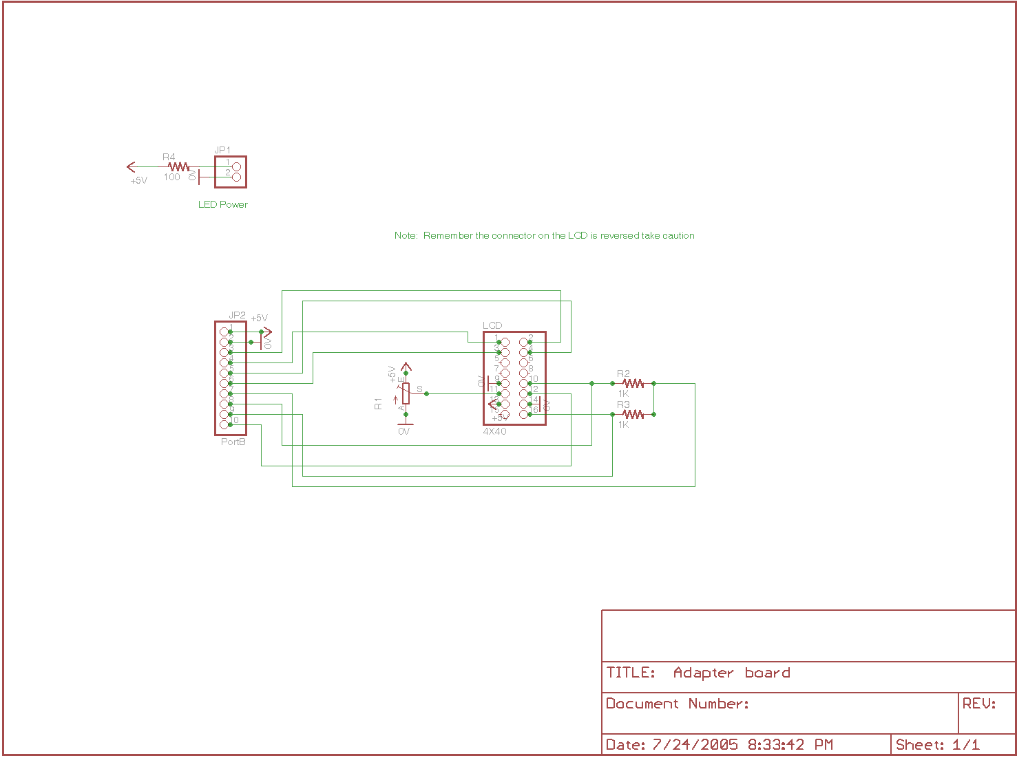
Here is how I made a 4x40 work

Code:
'****************************************************************
'*  Name    : USBladem4X40LCD                                    *
'*  Author  : Dave Cutliff                                      *
'*  Notice  : Copyright (c) 2005 Patent pending                 *
'*          : All Rights Reserved                               *
'*  Date    : 7/22/05                                           *
'*  Version : 1.0                                               *
'*  Notes   : PIC18F2455                                        *
'*          :  LCD 4X40 Dual driver                                                 *
'****************************************************************


Define  OSC     48
'**** LCD *******************************************************
'Set LCD Data port
DEFINE LCD_DREG PORTB
'Set starting Data bit (0 or 4) if 4-bit bus
DEFINE LCD_DBIT 4
'Set LCD Register Select port
DEFINE LCD_RSREG PORTB
'Set LCD Register Select bit
DEFINE LCD_RSBIT 0
'Set LCD Enable port
DEFINE LCD_EREG PORTB
'Set LCD Enable bit
DEFINE LCD_EBIT 3
'LCD RW Register PORT
'DEFINE LCD_RWREG PORTB
'LCD read/write pin bit
'DEFINE LCD_RWBIT 5
'Set LCD bus size (4 or 8 bits)
DEFINE LCD_BITS 4
'Set number of lines on LCD
DEFINE LCD_LINES 4
'Set command delay time in us
DEFINE LCD_COMMANDUS 2000
'Set data delay time in us
DEFINE LCD_DATAUS 50

LCD1_Disable    var portb.2
LCD2_Disable    var portb.1
'*** Program variables *****************************************
buffer1    Var    Byte[8]
buffer2    Var    Byte[8]
cnt    Var    Byte


lcdcnt     var  byte
'lcdchr     var  byte
lcdlen     var  byte
lcdline var byte
lcd var byte
lcdfunction var byte

'x          var  byte
'y          var  byte
'j          var  byte
k          var  byte
'ln         var  byte
'tmp1       var  byte
'***************************************************************
    USBInit
pause 500
' Initialize LCD
input LCD1_Disable
input LCD2_Disable
LCDOut $fe,1   'clear lcd
pause 100
LCDOut $fe,2   'home
LCDOut $fe,$0c 'Curser off
LCDOut "              USB 4X40 LCD   "
LCDOut $FE,$C0
LCDOut "              DAVE CUTLIFF    "
low LCD1_Disable
input LCD2_Disable
LCDOut $fe,1   'clear lcd
LCDOut $fe,2   'home
LCDOut $fe,$0c 'Curser off
LCDOut "         Highspeed USB Project  "
LCDOut $FE,$C0
LCDOut "             August 2005    "
pause 100
goto idleloop
'*********************subrouteens*************************
 READ_SETUP:
  USBService
  lcdlen = buffer1[3]
  lcdline = buffer1[1]
  lcdfunction = buffer1[2]
  lcd = buffer1[0]
    if lcd= 0 then
        input LCD1_Disable
        LOW LCD2_Disable
          else
        LOW LCD1_Disable
        input LCD2_Disable
    endif
  if lcdfunction = 1 then lcdout $FE,1
  lcdout $FE,lcdline

 RETURN

 Write_LCD:
      USBService
      lcdcnt = 1
      While lcdcnt < lcdlen
          for k = 1 to 7
          lcdcnt = lcdcnt + 1
          LCDOUT buffer2[k]
          if lcdcnt = lcdlen then goto outloop
          usbin 2, buffer2, cnt, idleloop
          next k

      wend
 Return


 outloop:
    USBService                                ' Must service USB regularly
    USBOut 1, buffer1, cnt, outloop            ' Send the bytes back
 return
'****************************************************************
' Wait for USB input of 8 numbers.
idleloop:
    USBService                                    ' Must service USB regularly
    cnt = 8                                        ' Specify input buffer size
    USBIn 1, buffer1, cnt, idleloop
    gosub READ_SETUP
    gosub outloop
    usbin 2, buffer2, cnt, idleloop
    GOSUB Write_LCD
    gosub outloop


goto idleloop
Hope this helps
Dave


Bookmarks