


Yup, Figured that out the other night.
It's them config words and assuming the compiler is doing what you want not what it was told to do. : )
posted the details on the Microchip site.
http://www.microchip.com/forums/m570397.aspx
===========================
I knew I just need to set another bit, well actually it was 3 bits.
You know what happens when you assUme.
Lesson learned:
1. don't assume the config words are set correctly shock
2. rtfm some more. LoL
RA5 is also OSCIN & CLKIN
Since the thing ran, I assumed the FOSC was set correctly by the compiler.
configword1 FOSC<2:0> was = 010 needed to be 100
bit 2-0 FOSC<2:0>: Oscillator Selection bits
111 =ECH: External Clock, High-Power mode (4-32MHz): device clock supplied to CLKIN pin
110 =ECM: External Clock, Medium-Power mode (0.5-4MHz): device clock supplied to CLKIN pin
101 =ECL: External Clock, Low-Power mode (0-0.5MHz): device clock supplied to CLKIN pin
100 =INTOSC oscillator: I/O function on CLKIN pin
011 =EXTRC oscillator: External RC circuit connected to CLKIN pin
010 =HS oscillator: High-speed crystal/resonator connected between OSC1 and OSC2 pins
001 =XT oscillator: Crystal/resonator connected between OSC1 and OSC2 pins
000 =LP oscillator: Low-power crystal connected between OSC1 and OSC2 pins
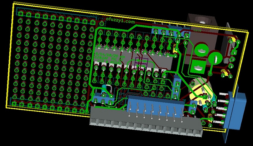
Okay, so now I can use the layout for my PCB without cutting.
PWM on the Backlight led will now work. mr green
Board specs:
1.5" x 1" prototyping area with a V+ & GND bus on the ends
RS-232 both 5v & full +/-12v via DB9
Use the PICkIT "PROG" connector to also talk to it via rs232-TTL uses RA3 (in) and RA0 (out)
LCD connectors for both styles of HD44780 Modules -- 1x16 & 2x8 on 0.1 centers
Laid out for the 14pin PIC to control the LCD so the remaining pins can be used for fun things. Even the 14pin Pic has 2 pins open.
Thanks for the help!
pcb schematic, layout and 3d by KICAD [free]
top view
PCB (c)2011 Ofuzzy1.com


Bookmarks