

Unless you're using the internal oscillator, you can't use RA5 as an output pin.


Unless you're using the internal oscillator, you can't use RA5 as an output pin.
Yup, Figured that out the other night.
It's them config words and assuming the compiler is doing what you want not what it was told to do. : )
posted the details on the Microchip site.
http://www.microchip.com/forums/m570397.aspx
===========================
I knew I just need to set another bit, well actually it was 3 bits.
You know what happens when you assUme.
Lesson learned:
1. don't assume the config words are set correctly shock
2. rtfm some more. LoL
RA5 is also OSCIN & CLKIN
Since the thing ran, I assumed the FOSC was set correctly by the compiler.
configword1 FOSC<2:0> was = 010 needed to be 100
bit 2-0 FOSC<2:0>: Oscillator Selection bits
111 =ECH: External Clock, High-Power mode (4-32MHz): device clock supplied to CLKIN pin
110 =ECM: External Clock, Medium-Power mode (0.5-4MHz): device clock supplied to CLKIN pin
101 =ECL: External Clock, Low-Power mode (0-0.5MHz): device clock supplied to CLKIN pin
100 =INTOSC oscillator: I/O function on CLKIN pin
011 =EXTRC oscillator: External RC circuit connected to CLKIN pin
010 =HS oscillator: High-speed crystal/resonator connected between OSC1 and OSC2 pins
001 =XT oscillator: Crystal/resonator connected between OSC1 and OSC2 pins
000 =LP oscillator: Low-power crystal connected between OSC1 and OSC2 pins
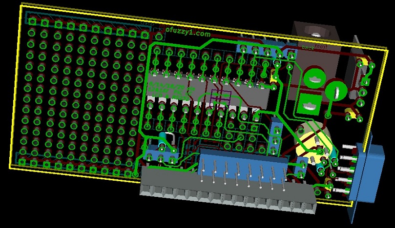
Okay, so now I can use the layout for my PCB without cutting.
PWM on the Backlight led will now work. mr green
Board specs:
1.5" x 1" prototyping area with a V+ & GND bus on the ends
RS-232 both 5v & full +/-12v via DB9
Use the PICkIT "PROG" connector to also talk to it via rs232-TTL uses RA3 (in) and RA0 (out)
LCD connectors for both styles of HD44780 Modules -- 1x16 & 2x8 on 0.1 centers
Laid out for the 14pin PIC to control the LCD so the remaining pins can be used for fun things. Even the 14pin Pic has 2 pins open.
Thanks for the help!
pcb schematic, layout and 3d by KICAD [free]
top view
PCB (c)2011 Ofuzzy1.com
Last edited by ofuzzy1; - 10th April 2011 at 08:48.

ofuzzy1 , Your layout look pretty good but I notice one thing. You would have to use a cable for the ICSP because it is too close to the coaxial power connector. I always lay my boards out so that you can plug the PicKit2 into them directly. Just my preference I pupose. I less cable to loose....
Dave Purola,
N8NTA
 Members who have read this thread : 0
You do not have permission to view the list of names.
 Posting Permissions

Bookmarks