


That looks fantastic. Too bad it's Proton Basic though. Thanks for sharing.
Very clever. What LCD did you use?
I have on my bench a Agilent N6705A that has many of he same functions. It only costs the price of a small car.
Hi there,
Thanks for your comment. Anyway I used 128X64 Samsung KS0108 Graphic LCD and matrix keypad which I converted to PS2, or any PS2 numeric keypad.
Cheers

Interesting project.
Are you using PID to control the output voltage?
Ioannis
I'm guessing from the thread title that OP is using an external DAC - so PID is not needed. The MCU's I use have a built-in (dual-channel) 12-bit DAC and I have done something similar. The DAC output is scaled to 2V full scale. An op-amp (rail-to-rail) buffer with 6x gain and a simple linear output stage gives 0-12V output with 3mV resolution.
Why pay for overpriced toys when you can have
professional grade tools for FREE!!!
If it is open loop, how is the output voltage regulated with the load?
Feedback is required, isn't it?
Ioannis
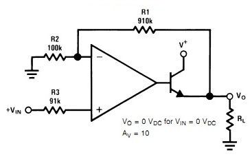
That is the purpose of the op-amp/buffer as in the figure below - the DAC provides the Vin. The gain is changed by altering the values of the feedback resistor pair R1, R2. Gain = (R1+R2)/R2.
Why pay for overpriced toys when you can have
professional grade tools for FREE!!!
OK, it is the Vref voltage of the loop that is controlled. So the PIC is not in the output voltage loop.
OK, it has some cons, but with a high resolution DAC it will work just fine.
In fact I ordered a couple of MAX5541, 16bit DACs to play with the idea and build a digital controled Power Supply. One for the voltage and the other for he current.
My dream I had from childhood...
Ioannis
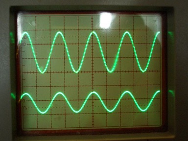
Using this method (MCU->Hi-Res DAC->Buffer/Amp), you can not only make the digitally controlled power supply of your childhood dreams but you can also turn it into a fully programmable unit that can generate all kinds of waveforms - very useful for test purposes. For example you can program it to generate stuff like sine, triangle, sawtooth, staircase and other custom waveforms. The trace below is a sine waveform generated by a 12-bit DAC. The timebase is 10uS/Div so the frequency is 40KHz.
Why pay for overpriced toys when you can have
professional grade tools for FREE!!!
Yeap, that is the main idea.
Not exactly to make a Power supply act like waveform generator but have it under some kind of profile control.
E.g. for test of regulators steping the input voltage or slow starting power to load and see if it resets normaly etc.
Ioannis
can some one send me the files please
schematic for this power supply
there is a link in the start of video but it is a dead link :/
I never downloaded the "code". But it seems to just be a sales pitch, from reading the posts: http://www.protonbasic.co.uk/archive...p/t-54946.html
http://www.scalerobotics.com
thanks for your help but i need schematic for this power supply and not the code i don't have problem with the codeOriginally Posted by ScaleRobotics

If you go to that link scale posted and there is a link there where you can donwload the shcematic and PCB
Edit sorry just looked and it's and old version, I did have the schematic but would have to dig deep for it
Last edited by chuck; - 22nd June 2012 at 19:00.
i am very interesting to this power supply? where I can download schematic of power supply
That looks fantastic. Too bad it's Proton Basic though. Thanks for sharing.
 Members who have read this thread : 0
You do not have permission to view the list of names.
 Posting Permissions


Bookmarks