

Thermistor I guess. ICL


Thermistor I guess. ICL
Last edited by mister_e; - 27th January 2011 at 17:37.
Steve
It's not a bug, it's a random feature.
There's no problem, only learning opportunities.

Hello all, I am back to trying to get this done. Any suggestions on the transformer in the melabs example? I don't need the power supply side, so really I guess I just need the zero crossing sync.
So basiclly, a logic level TRAIC (as linked by Dave) connected to an output and a way to detect the Zero crossing is all I need, Yes?
-Bert
The glass is not half full or half empty, Its twice as big as needed for the job!
http://foamcasualty.com/ - Warbird R/C scratch building with foam!

Exactly.Originally Posted by cncmachineguy

The transformer must be rated for at least the maximum power you would expect to use plus a margin for safety. Since the VA rating defines the power, you could be very adaptable on the choice of transformer in terms of volts and current but, generally speaking, keeping the volts low (<24VAC) and the current high (probably around 3A to 5A) is safer for the user.
There would be a quite large selection available on the likes of eBay if you search.
half asleep, but here is my beginning. Looking for some help here if anyone wants to help me fix this
-Bert
The glass is not half full or half empty, Its twice as big as needed for the job!
http://foamcasualty.com/ - Warbird R/C scratch building with foam!
The cool thing of Triac is they often come short when they burn. So ask yourself if it's safe to plug it to the Main first. If the wire break... how dangerous it will be if someone try to change it LIVE.
Kinda stuff like that
Steve
It's not a bug, it's a random feature.
There's no problem, only learning opportunities.

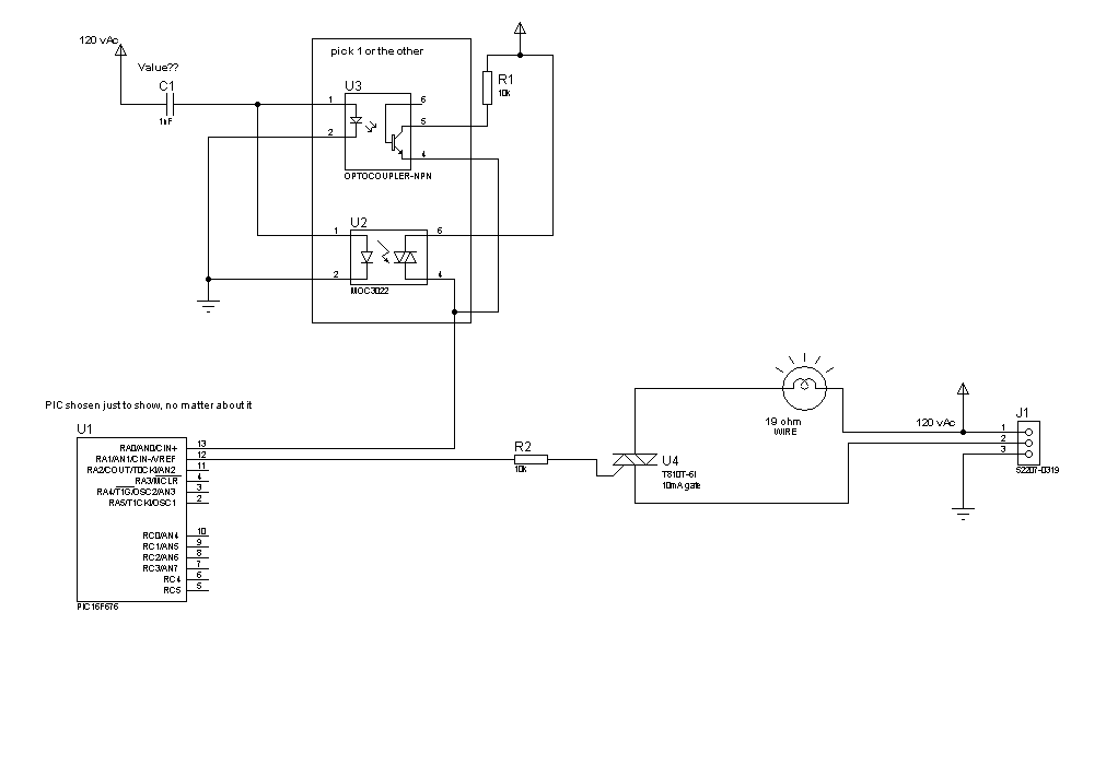
I recommend you look up the MOC3021 opto-triac to interface your triac to the PIC. Your current scheme does not seem workable.
About my schematic: The values for the resistors are just the default values. I know they are not correct. The cap for the input to the opto's, I have no idea what value this should be. Also have no idea yet as to which opto style I want for the zero crossing side of things. Maybe neither? And I see I have connected the top opto incorrectly. I ment to groung the emitter and take the signal from the collector.
@ Steve, Are you trying to remind me I need a fuse on the wire side?
@Jerson, I am under the impression using a logic Triac, with 10mA gate will work as I drew it. If I am wrong about this, feel free to tell me and I will add the opto.
@ Moderators, if this should now be moved to the schematic section, please move it. Thanks
Last edited by cncmachineguy; - 4th May 2011 at 12:55. Reason: added message to mods
-Bert
The glass is not half full or half empty, Its twice as big as needed for the job!
http://foamcasualty.com/ - Warbird R/C scratch building with foam!
 Members who have read this thread : 0
You do not have permission to view the list of names.
 Posting Permissions
Bookmarks