 Re: Stable ADC readings
Hervé, je veux bien t'aider du mieux que je peut, mais tu va devoir faire une partie des devoirs de ton coté.
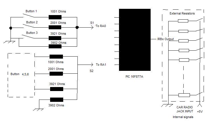
Ok, let's observe the schematic you posted

OK, please answer the following question:
Q1: The Resistor attached to the button are built-in the remote/Steering and you can't modify anything in right?
A1:_______________________________________
Q2: You have a 10K pull-up On RA0, and another on RA1... true?
A2:________________________________________
Q3: If so, assuming you don't push on any button, Between GND and RA0 AND between GND and RA1 with your multimeter you should read something like 1.4Volt RIGHT?
A3:________________________________________
From there, we need to etablish at least 4 conditions
1) ADC reading when no push button are pressed
2) ADC Reading when you push on Button 1 alone
3) ADC Reading when you push on Button 2 alone
4) ADC Reading when you push on Button 3 alone
We can use maths to do so OR output each ADC reading to a LCD OR send the data do your PC via serial communication OR store them in the PIC EEPROM. Choice is yours. Let's see if the maths could work here.
Without any push button pressed, I said around 1.4. Using the voltage divider theory
(3902/(3902+10000))*5 = 1.403
so the ADC should return something like
(1.4/5)*1023 = 287
Do the same with the other resistor value and you should be able to evaluate
1) when no push button are pressed
V = 1.4
ADC Reading = 287
2) When you push on Button 1 alone
V = 0.37
ADC Reading = 76
3) When you push on Button 2 alone
V = 0.58
ADC Reading = 119
4) When you push on Button 3 alone
V = 0.82
ADC Reading = 168
Now, try this.
Code:
'
'       Hardware setup
'       ==============
        '
        '       I/O
        '       ---
        TRISA = %00000011       ' RA0 et RA1 en entrée
        TRISB = 255             ' Disconnect all resistor from the circuit
        PORTB = 0               '
        '
        '       ADC
        '       ---
        DEFINE ADC_BITS 10      ' Set number of bits in result
        DEFINE ADC_CLOCK 3      ' Set clock source (rc = 3)
        DEFINE ADC_SAMPLEUS 50  ' Set sampling time in
        ADCON1 = %10000010      ' RA0 à RA3

'
'       Software Variable
'       =================
        ADRes       VAR WORD    ' ADC Reading
        BTN         var byte    ' Data to be sent to PORTB
        i           VAR BYTE    '
        ADCChannel  VAR BIT     '
        ADCButton   VAR BYTE [3]'
'
'       Software constant
'       =================
        ADCSafety   CON 10              ' min/max range for ADC Reading
                                        '
        ADCNone     CON 287 - ADCSafety '
        ADCButton[0]  = 76              ' button 1 or 4
        ADCButton[1]  = 119             ' button 2 or 5
        ADCButton[2]  = 168             ' button 3 or 6

Start:
        TRISB = 255                     ' Disconnect all resistor from the circuit
        ADCIN ADCChannel,ADRes          ' Read ADC
                                        '
        if (ADRes < ADCNone) Then       ' Any button down?!?
                                        ' - Yes!
                FOR i = 2 TO 0 STEP -1  '   Loop through all 3 calculated posibilities
                                        '   Test against calculated ADCresult
                                        '   and allow a range of +/- ADCSafety
                        IF (ADRes > (ADCButton[i]-ADCSafety)) AND  (ADRes < (ADCButton[i]+ADCSafety)) THEN
                                        '   Valid ADC result, clear the coresponding I/O
                                TRISB = ((DCD i) << (ADCChannel*3)) ^255
                                PAUSE 200
                                i=0     '   and getOut of here
                                ENDIF   '
                                        '
                        NEXT            '
                                        '
                else                    ' - NO!
                                        '   Switch to the other ADC channel
                ADCChannel = ADCChannel ^ 1
                ENDIF
        GOTO Start                      '
Button 1, enable PORTB.0, Button 2 PORTB.1 etc etc.
For testing purpose use LEDs to VDD. It works here.
Steve
It's not a bug, it's a random feature.
There's no problem, only learning opportunities.


Bookmarks