Hi,
It's my first time using a MAX6675 k-type thermocouple converter and got it to work thanks to (99%) of the info in this thread  .
.
AAMOF, I had to modify one info found above and it is about bit shifting.
First, my working code (and hopefully correct) is:
Code:
' ====== FUSES ====================================================================================
' PIC 16F690
@ __Config _FCMEN_OFF &_IESO_OFF &_CPD_OFF &_WDT_OFF &_INTRC_OSC_NOCLKOUT &_BOR_OFF &_CP_OFF &_PWRTE_OFF &_MCLRE_OFF

' ====== REGISTERS ================================================================================
'             76543210
OPTION_REG = %10000000 ' PORT A&B Pull-Ups disabled (see WPUA & WPUB)
OSCCON     = %01100000 ' Internal RC set to 4Mhz - not to be used with XTal
ANSEL      = %00000000 ' Analog inputs Channels Bit<0>=0 to Bit<7>=7
ANSELH     = %00000000 ' Analog inputs Channels Bit<0>=8 to Bit<3>=11
ADCON0     = %00000000 ' A/D Module OFF
CM1CON0    = %00000000 ' Comparator1 Module is OFF
CM2CON0    = %00000000 ' Comparator2 Module is OFF
INTCON     = %00000000 ' INTerrupts CONtrol
PORTA      = %00000000 ' Ports High/Low (0 to 5)
TRISA      = %00000000 ' Set Input/Output (0 to 5)
PORTB      = %00100000 ' Ports High/Low (4 to 7) B5=MAX6675-CS
TRISB      = %00010000 ' Set Input/Output (4 to 7) B4=MAX6675-SDO
PORTC      = %00000000 ' Ports High/Low (0 to 7)
TRISC      = %00000000 ' Set Input/Output (0 to 7)

' ====== DEFINES ==================================================================================
DEFINE OSC 4

DEFINE SHIFT_PAUSE 250  'for MAX6675 conversion time

DEFINE LCD_DREG PORTC   'LCD data port
DEFINE LCD_DBIT 0       'LCD data starting bit 0 or 4 on µC
DEFINE LCD_RSREG PORTC  'LCD Register Select port
DEFINE LCD_RSBIT 4      'LCD Register Select bit
DEFINE LCD_EREG PORTC   'LCD Enable port
DEFINE LCD_EBIT 5       'LCD Enable bit
DEFINE LCD_BITS 4       'LCD bus size 4 or 8
DEFINE LCD_LINES 2      'Line number on LCD

' ====== VARIABLES ================================================================================
MAX6675_SDO var PORTB.4
MAX6675_CS  var PORTB.5
MAX6675_SCK var PORTB.6

RawTemp     var word
RawTemp     = 0
Temp        var byte
Temp        = 0
TempUnit    var byte
TempUnit    = 0
TempDec     var byte
TempDec     = 0

' ====== PROGRAM ==================================================================================

PAUSE 500   ' time for LCD to settle

MAX6675_READ:

  MAX6675_CS = 0
  shiftin MAX6675_SDO,MAX6675_SCK,0,[RawTemp\16] 'mode is MSBPRE
  MAX6675_CS = 1

  Temp = RawTemp >> 2

  TempUnit = Temp / 10 'get temperature Units for display
  TempDec =  Temp MOD 10 'get temperature Decimals for display
  lcdout $FE, $80,"BIN ", BIn16 Rawtemp
  lcdout $FE, $C0,"Tmp ", DEC TempUnit,".",dec TempDec," C"

  PAUSE 1000

GOTO MAX6675_READ
END
According to the MAX6675 datasheet: "Read the 16 output bits on the falling edge of the clock. The first bit, D15, is a dummy sign bit and is always zero. Bits D14D3 contain the converted temperature in the order of MSB to LSB".
If I get it well, when reading the termocouple, I get 16 bits and I need to "keep" bits 14 to 3.
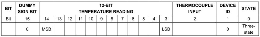
So, to get the (what I hope is correct) right value, why do I have to shift by "2" instead of what has been said above (shift by 3) or even shift by 1 since bit 14 is the second bit to start with?


Bookmarks