

You can view the page at http://www.picbasic.co.uk/forum/cont...onsole-Project


You can view the page at http://www.picbasic.co.uk/forum/cont...onsole-Project
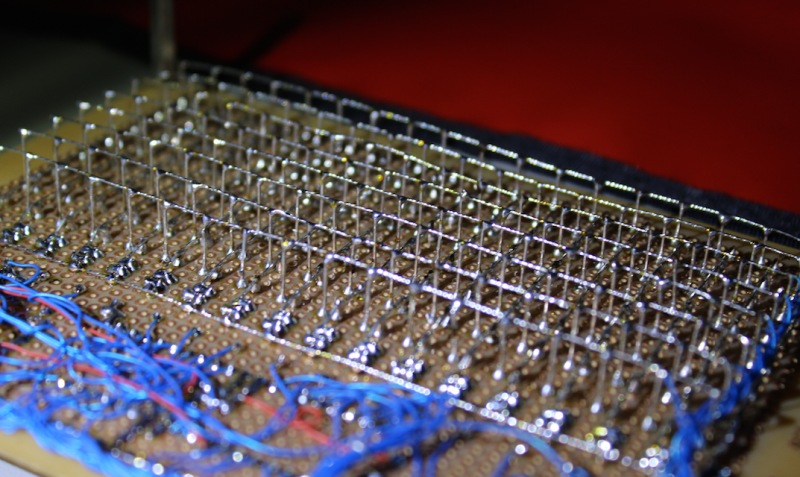
The prototype looks cool - Can you also include a picture of the underside of the build

I have added it to the Wiki.Originally Posted by malc-c

very neat wiring -
Hello Art and all,
I downloaded the last 144_LED_V3.zip and I found some diferences in the schematics.
In 144LEDGAME-Schematic.pdf the keys (UP/DOW/LEFT/RIGHT) is wired by resistors to ground and active in High level.
In SchematicB.bmp UP/RIGHT is wired by resistors to VCC (active in Low level) and LEFT/DOWN is wired byr resistors to Ground (active in High level).
What is the correct schematic ?
I am building this hardware and would like to know the correct mode to work fine.
Other thing, in SchematicB.bmp the A.0 is wired only to resistor and UP key, but in SchematicA.bmp is wired to the led! What is the correct?
Thanks
So it’s 5 years to the month since making the three of them, and I have two left.
Funny this stuff hardly ever comes out once I’m done with them, but I got a new camera for Christmas so…
[
With regard to porta.0, after 5 yrs I’d do the same thing you should and look at what
the pin is used for. Four pins must be used for the joystick.
 Members who have read this thread : 0
You do not have permission to view the list of names.
 Posting Permissions

Bookmarks