New approach to Rotary Encoder


Closed Thread
Results 1 to 40 of 91

Hybrid View

  1. #1
    Join Date
    Dec 2008
    Location
    Ploiesti, ROMANIA
    Posts
    582


    Did you find this post helpful? Yes | No

    Default Re: New approach to Rotary Encoder

    Thanks to Mr.Henrik Olsson this code work PERFECT !!! I'm sure I would not have done it without his help !
    Code:
    Main:
        PortA.1 = 0
        newState = PortA & 011100        
        PortA.1 = 1
    
        If newState <> 28 THEN
            If newState <> oldState THEN
                  
                Select Case oldState
                    Case 12
                    If NewState = 20 THEN dir=up       
                    If NewState = 24 THEn dir=dn
                    
                    Case 20
                    If NewState = 24 THEN dir=up               
                    If NewState = 12 THEN dir=dn
                   
                    Case 24
                    If NewState = 12 THEN dir=up                       
                    If NewState = 20 THEN dir=dn
                END SELECT
    
                GOSUB UpOrDn 
    
        PortA.1 = 0
        OldState = PortA & 011100         
        PortA.1 = 1
                   
           endif          
        ENDIF
    Goto Main

  2. #2
    Join Date
    Sep 2011
    Posts
    5


    Did you find this post helpful? Yes | No

    Default Re: New approach to Rotary Encoder

    Hi to all. I want to use a rotary encoder with a 18f252, and i have a lot of troubles. I want to use interupts, so my only solution PORTB or I can use Portc also?

    I made a pcb and I made the connections to PORTC, and I also use a debounce circuit, which I think causes problems. Anyone has a snipset code cause I do not have any expieriance with encoders?
    5v
    __|__
    | |
    / /
    \ \
    /10k / 10K
    \ \
    | A | B ENC
    - -
    | |-------------------------------
    \ |
    /10K \
    \ /10K
    / \
    |--------------------- |--------------------
    PORTC.2 | PORTC.3 |
    ---- ----- 100nF
    ---- -----
    | |
    --------- -----------
    ----- -----
    - -
    Last edited by kzeoprf; - 21st August 2012 at 10:49.

  3. #3
    Join Date
    Oct 2005
    Location
    Sweden
    Posts
    3,624


    Did you find this post helpful? Yes | No

    Default Re: New approach to Rotary Encoder

    Hello,
    On the 18F252 there's no interrupt capabillity on PortC.

    Your schematic really doesn't show up that good here but it LOOKS like you have a 10k from 5V to the "top" of each of the switches in the encoders, then the other side of each switch thru another 10k to the input with a 100nF cap to GND, is that correct?

    If the above is not correct please post a proper schematic for us to see.
    If the above IS correct then it's not a very good hardware design IMHO. When the switch in the ecoder is closed you have 2*10k in series to the input, decoupled by a 100nF cap, this may be fine. But when the switch is open there's no path for the capacitor to discharge except thru the fairly high input impedance of the pin. In effect the pin floats which is not a good thing for inputs.

    /Henrik.

  4. #4
    Join Date
    Jan 2005
    Location
    Montreal, Quebec, Canada
    Posts
    3,172


    Did you find this post helpful? Yes | No

    Default Re: New approach to Rotary Encoder

    I finally got around to trying my rotary encoders out on an 18F24K22 using DT interrupts.

    I kept things simple; checking for only 1 movement per click (detent). This encoder also has a momentary ON switch.


    Code:
    '***************************************************************************
    '*  Name    : 18F24K22 encoder.pbp                                         *
    '*  Author  : Demon                                                 *
    '*  Date    : Sep 5 2012                                                   *
    '*  Version : 1.0                                                          *
    '*  Hardware : PIC 18F24K22, internal oscillator, 8 MHz                    *
    '*           : ICSP                                                        *
    '*           : MeLabs U2 Programmer v4.32                                  *
    '*  Software : PIC Basic Pro v2.60C                                        *
    '*           : MicroCode Studio Plus v2.2.1.1                              *
    '*           : MPASM v5.46                                                 *
    '*  CONFIG   : - if you use these, you must comment the ones in the        *
    '                .INC file in PBP folder                                   *
    '              - available options at the bottom of P*.INC file in         *
    '                MPLAB TOOLS/MPASM SUITE folder                            *
    '***************************************************************************
    asm
     __CONFIG    _CONFIG1H, _FOSC_INTIO67_1H & _PLLCFG_OFF_1H & _PRICLKEN_ON_1H & _FCMEN_OFF_1H & _IESO_OFF_1H
     __CONFIG    _CONFIG2L, _PWRTEN_ON_2L & _BOREN_SBORDIS_2L & _BORV_285_2L
     __CONFIG    _CONFIG2H, _WDTEN_OFF_2H
     __CONFIG    _CONFIG3H, _PBADEN_ON_3H & _HFOFST_OFF_3H & _MCLRE_EXTMCLR_3H
     __CONFIG    _CONFIG4L, _STVREN_ON_4L & _LVP_OFF_4L & _XINST_OFF_4L & _DEBUG_OFF_4L
    endasm
    
    ;--- Oscillator speed ------------------------------------------------------
    
    DEFINE OSC 8
    CLEAR
    
    ;--- Setup Interrupts ------------------------------------------------------
    INCLUDE "DT_INTS-18.bas"        ; Base Interrupt System
    INCLUDE "ReEnterPBP-18.bas"     ; PBP Re-entry for external interrupt
    
    ASM
    INT_LIST  macro    ; IntSource,        Label,  Type, ResetFlag?
            INT_Handler    INT_INT,  _ExternalInterrupt0,   PBP,  yes
        endm
        INT_CREATE               ; Creates the interrupt processor
    ENDASM
    
    @   INT_ENABLE   INT_INT     ; enable external (INT) interrupts
    
    ;--- Setup Registers -------------------------------------------------------
    
    OSCCON = %01100110              ' OSCILLATOR CONTROL REGISTER
    OSCTUNE = %00000000             ' OSCILLATOR TUNING REGISTER
    
    PMD0 = %11111111                ' PERIPHERAL MODULE DISABLE REGISTER 0
    PMD1 = %11111111                ' PERIPHERAL MODULE DISABLE REGISTER 1
    PMD2 = %00001111                ' PERIPHERAL MODULE DISABLE REGISTER 2
    
    INTCON2=%10000100               ' INTERRUPT CONTROL 2 REGISTER
    
    ANSELA = 0                      ' Digital I/O
    ANSELB = 0                      ' Digital I/O
    ANSELC = 0                      ' Digital I/O
    
    ;--- Setup Port directions -------------------------------------------------
    
    TRISA = %00000000               ' Set port A pins to output
    TRISB = %00000001               ' Set port B pin 0 to input, others output
    TRISC = %00000110               ' Set port C pins 1,2 to input, others output
    
    ;--- Pins ------------------------------------------------------------------
    
    WiperA      VAR PortB.0         ' Interrupt 0
    WiperB      VAR PortC.2
    
    Switch      VAR PortC.1
    
    LedPower    VAR PortB.5
    
    ;--- Variables -------------------------------------------------------------
    
    LEDS        VAR BYTE            ' 8 Leds connected on Port A
    
    ;--- Program Start ---------------------------------------------------------
    
    start:
    
    Pause 200                       ' Let PIC stabilize
    
    Ledpower = 0
    
    Leds = %00000001
    PortA = leds
    
    ;--- The Main Loop ---------------------------------------------------------
    
    mainloop:
    
      if Switch = 1 then
        Ledpower = 1                    ' Turn ON Led
        pause 200                       ' Debounce
        Ledpower = 0                    ' Turn it back OFF
      endif
    
      Goto mainloop
    
    end
    
    '---[INT - interrupt handler]---------------------------------------------------
    ExternalInterrupt0:
      if wiperb = 1 then
        if leds.7 = 0 then
          LEDS = LEDs << 1              ' Leds blink counter-clockwise
        endif
      else
        if leds.0 = 0 then
          leds = leds >> 1              ' Leds blink clockwise
        endif
      endif
    
      PortA = leds
      pause 100
    @ INT_RETURN

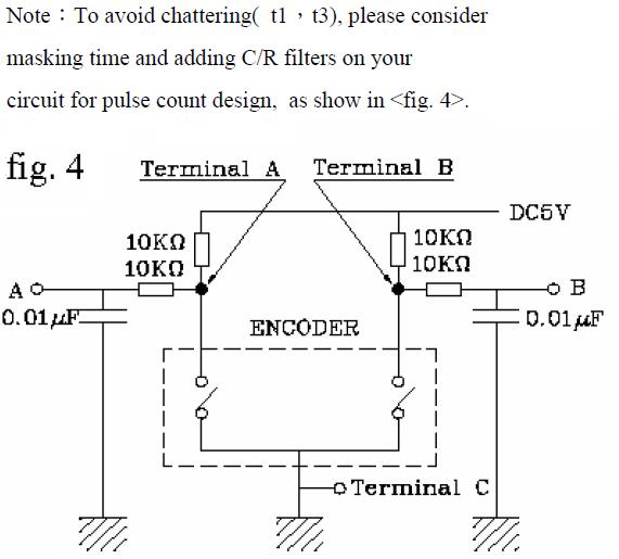
    I used both 0.01uF and 0.1uF caps to improve debounce and wired the C pin straight to Vss (only check wiper A and B). This is the recommended circuit by the manufacturer:

    Name:  Encoder debounce.JPG
Views: 14799
Size:  39.3 KB

    Robert
    Last edited by Demon; - 4th October 2016 at 17:35.

  5. #5
    Join Date
    Nov 2003
    Location
    Greece
    Posts
    4,172


    Did you find this post helpful? Yes | No

    Default Re: New approach to Rotary Encoder

    Nice try Robert.

    I only object to the use of Pause 100 inside the ISR.

    Ioannis

  6. #6
    Join Date
    Jan 2005
    Location
    Montreal, Quebec, Canada
    Posts
    3,172


    Did you find this post helpful? Yes | No

    Default Re: New approach to Rotary Encoder

    Quote Originally Posted by Ioannis View Post
    Nice try Robert.

    I only object to the use of Pause 100 inside the ISR.

    Ioannis

    I had first added PAUSE to reduce jitter, the only debounce I could think of on short notice. But adding 0.1uF caps as suggested in this thread was the key. I left the 0.01uF caps in, they can't hurt.

    I now removed the PAUSE and it works even better (faster response time).

    Thanks!

    Robert
    Last edited by Demon; - 7th September 2012 at 22:55. Reason: type faster than my brain

  7. #7
    Join Date
    Jan 2005
    Location
    Montreal, Quebec, Canada
    Posts
    3,172


    Did you find this post helpful? Yes | No

    Default Re: New approach to Rotary Encoder

    Changes:

    - used a low priority interrupt for the switch to free up Main Routine for other logic.
    - added comments for the registers.
    - used constants (I remember something about improved efficiency, this is just to get in the habit).
    - PAUSE in low priority interrupt does not cause problems.

    Robert

    Code:
    '***************************************************************************
    '*  Name    : 18F24K22 encoder.pbp                                         *
    '*  Author  : Demon                                                 *
    '*  Date    : Sep 5 2012                                                   *
    '*  Version : 1.0                                                          *
    '*  Notes   : Test program                                                 *
    '*  Hardware : PIC 18F24K22, internal oscillator, 8 MHz                    *
    '*           : ICSP                                                        *
    '*           : MeLabs U2 Programmer v4.32                                  *
    '*  Software : PIC Basic Pro v2.60C                                        *
    '*           : MicroCode Studio Plus v2.2.1.1                              *
    '*           : MPASM v5.46                                                 *
    '*  CONFIG   : - if you use these, you must comment the ones in the        *
    '                .INC file in PBP folder                                   *
    '              - available options at the bottom of P*.INC file in         *
    '                MPLAB TOOLS/MPASM SUITE folder                            *
    '***************************************************************************
    asm
     __CONFIG    _CONFIG1H, _FOSC_INTIO67_1H & _PLLCFG_OFF_1H & _PRICLKEN_ON_1H & _FCMEN_OFF_1H & _IESO_OFF_1H
     __CONFIG    _CONFIG2L, _PWRTEN_ON_2L & _BOREN_SBORDIS_2L & _BORV_285_2L
     __CONFIG    _CONFIG2H, _WDTEN_OFF_2H
     __CONFIG    _CONFIG3H, _PBADEN_ON_3H & _HFOFST_OFF_3H & _MCLRE_EXTMCLR_3H
     __CONFIG    _CONFIG4L, _STVREN_ON_4L & _LVP_OFF_4L & _XINST_OFF_4L & _DEBUG_OFF_4L
    endasm
    
    ;--- Oscillator speed ------------------------------------------------------
    
    DEFINE OSC 8
    CLEAR
    
    ;--- Setup Interrupts ------------------------------------------------------
    DEFINE USE_LOWPRIORITY 1
    
    INCLUDE "DT_INTS-18.bas"        ; Base Interrupt System
    INCLUDE "ReEnterPBP-18.bas"     ; PBP Re-entry for external interrupt
    INCLUDE "ReEnterPBP-18LP.bas"   ; PBP Re-entry for low priority external interrupt
    
    ASM
    ;----[High Priority Interrupts] --------------------------------------------
    INT_LIST  macro    ; IntSource,        Label,  Type, ResetFlag?
            INT_Handler    INT0_INT,  _ExternalInterrupt0,   PBP,  yes
        endm
        INT_CREATE                  ; Creates the interrupt processor
    
    ;----[Low Priority Interrupts] ---------------------------------------------
    INT_LIST_L  macro  ; IntSource,        Label,  Type, ResetFlag?
            INT_Handler    INT1_INT,  _ExternalInterrupt1,   PBP,  yes
        endm
        INT_CREATE_L                ; Creates the Low Priority interrupt processor
    
    ;----[Enable Interrupts] ---------------------------------------------------
        INT_ENABLE   INT0_INT       ; Enable (INT0) external interrupt
        INT_ENABLE   INT1_INT       ; Enable (INT1) external interrupt
    ENDASM
    
    INTCON2.7=1
    '   bit 7   RBPU: PORTB Pull-up Enable bit
    '               1 = All PORTB pull-ups are disabled
    '               0 = PORTB pull-ups are enabled provided that the pin is an input and the
    '                   corresponding WPUB bit is set.
    
    INTCON2.6=0
    '  bit 6   INTEDG0: External Interrupt 0 Edge Select bit
    '               1 = Interrupt on rising edge
    '               0 = Interrupt on falling edge
    
    INTCON2.5=1
    '  bit 5   INTEDG1: External Interrupt 1 Edge Select bit
    '               1 = Interrupt on rising edge
    '               0 = Interrupt on falling edge
    
    INTCON2.4=0
    '  bit 4   INTEDG2: External Interrupt 2 Edge Select bit
    '               1 = Interrupt on rising edge
    '               0 = Interrupt on falling edge
    
    ;--- Setup Registers -------------------------------------------------------
    
    OSCCON = %01100110              ' OSCILLATOR CONTROL REGISTER
    '  bit 7   IDLEN: Idle Enable bit
    '              1 = Device enters Idle mode on SLEEP instruction
    '              0 = Device enters Sleep mode on SLEEP instruction
    '  bit 6-4 IRCF<2:0>: Internal RC Oscillator Frequency Select bits(2)
    '            111 = HFINTOSC – (16 MHz)
    '            110 = HFINTOSC/2 – (8 MHz)
    '            101 = HFINTOSC/4 – (4 MHz)
    '            100 = HFINTOSC/8 – (2 MHz)
    '            011 = HFINTOSC/16 – (1 MHz)(3)
    '       If INTSRC = 0 and MFIOSEL = 0:
    '            010 = HFINTOSC/32 – (500 kHz)
    '            001 = HFINTOSC/64 – (250 kHz)
    '            000 = LFINTOSC – (31.25 kHz)
    '       If INTSRC = 1 and MFIOSEL = 0:
    '            010 = HFINTOSC/32 – (500 kHz)
    '            001 = HFINTOSC/64 – (250 kHz)
    '            000 = HFINTOSC/512 – (31.25 kHz)
    '       If INTSRC = 0 and MFIOSEL = 1:
    '            010 = MFINTOSC – (500 kHz)
    '            001 = MFINTOSC/2 – (250 kHz)
    '            000 = LFINTOSC – (31.25 kHz)
    '       If INTSRC = 1 and MFIOSEL = 1:
    '            010 = MFINTOSC – (500 kHz)
    '            001 = MFINTOSC/2 – (250 kHz)
    '            000 = MFINTOSC/16 – (31.25 kHz)
    '  bit 3   OSTS: Oscillator Start-up Time-out Status bit
    '              1 = Device is running from the clock defined by FOSC<3:0> of the CONFIG1H register
    '              0 = Device is running from the internal oscillator (HFINTOSC, MFINTOSC or LFINTOSC)
    '  bit 2   HFIOFS: HFINTOSC Frequency Stable bit
    '              1 = HFINTOSC frequency is stable
    '              0 = HFINTOSC frequency is not stable
    '  bit 1-0 SCS<1:0>: System Clock Select bit
    '             1x = Internal oscillator block
    '             01 = Secondary (SOSC) oscillator
    '             00 = Primary clock (determined by FOSC<3:0> in CONFIG1H).
    
    OSCCON2 = %00000100              ' OSCILLATOR CONTROL REGISTER 2
    '  bit 7   PLLRDY: PLL Run Status bit
    '               1 = System clock comes from 4xPLL
    '               0 = System clock comes from an oscillator, other than 4xPLL
    '  bit 6   SOSCRUN: SOSC Run Status bit
    '               1 = System clock comes from secondary SOSC
    '               0 = System clock comes from an oscillator, other than SOSC
    '  bit 5   Unimplemented: Read as ‘0’.
    '  bit 4   MFIOSEL: MFINTOSC Select bit
    '               1 = MFINTOSC is used in place of HFINTOSC frequencies of 500 kHz, 250 kHz and 31.25 kHz
    '               0 = MFINTOSC is not used
    '  bit 3   SOSCGO(1): Secondary Oscillator Start Control bit
    '               1 = Secondary oscillator is enabled.
    '               0 = Secondary oscillator is shut off if no other sources are requesting it.
    '  bit 2   PRISD: Primary Oscillator Drive Circuit Shutdown bit
    '               1 = Oscillator drive circuit on
    '               0 = Oscillator drive circuit off (zero power)
    '  bit 1   MFIOFS: MFINTOSC Frequency Stable bit
    '               1 = MFINTOSC is stable
    '               0 = MFINTOSC is not stable
    '  bit 0   LFIOFS: LFINTOSC Frequency Stable bit
    '               1 = LFINTOSC is stable
    '               0 = LFINTOSC is not stable
    
    OSCTUNE = %00000000             ' OSCILLATOR TUNING REGISTER
    '  bit 7   INTSRC: Internal Oscillator Low-Frequency Source Select bit
    '               1 = 31.25 kHz device clock derived from the MFINTOSC or HFINTOSC source
    '               0 = 31.25 kHz device clock derived directly from LFINTOSC internal oscillator
    '  bit 6   PLLEN: Frequency Multiplier 4xPLL for HFINTOSC Enable bit(1)
    '               1 = PLL enabled
    '               0 = PLL disabled
    '  bit 5-0 TUN<5:0>: Frequency Tuning bits – use to adjust MFINTOSC and HFINTOSC frequencies
    '          011111 = Maximum frequency
    '          011110 =
    '          • • •
    '          000001 =
    '          000000 = Oscillator module (HFINTOSC and MFINTOSC) are running at the factory
    '                   calibrated frequency.
    '          111111 =
    '          • • •
    '          100000 = Minimum frequency
    
    PMD0 = %11111111                ' PERIPHERAL MODULE DISABLE REGISTER 0
    '  bit 7   UART2MD: UART2 Peripheral Module Disable Control bit
    '               1 = Module is disabled, Clock Source is disconnected, module does not draw digital power
    '               0 = Module is enabled, Clock Source is connected, module draws digital power
    '  bit 6   UART1MD: UART1 Peripheral Module Disable Control bit
    '               1 = Module is disabled, Clock Source is disconnected, module does not draw digital power
    '               0 = Module is enabled, Clock Source is connected, module draws digital power
    '  bit 5   TMR6MD: Timer6 Peripheral Module Disable Control bit
    '               1 = Module is disabled, Clock Source is disconnected, module does not draw digital power
    '               0 = Module is enabled, Clock Source is connected, module draws digital power
    '  bit 4   TMR5MD: Timer5 Peripheral Module Disable Control bit
    '               1 = Module is disabled, Clock Source is disconnected, module does not draw digital power
    '               0 = Module is enabled, Clock Source is connected, module draws digital power
    '  bit 3   TMR4MD: Timer4 Peripheral Module Disable Control bit
    '               1 = Module is disabled, Clock Source is disconnected, module does not draw digital power
    '               0 = Module is enabled, Clock Source is connected, module draws digital power
    '  bit 2   TMR3MD: Timer3 Peripheral Module Disable Control bit
    '               1 = Module is disabled, Clock Source is disconnected, module does not draw digital power
    '               0 = Module is enabled, Clock Source is connected, module draws digital power
    '  bit 1   TMR2MD: Timer2 Peripheral Module Disable Control bit
    '               1 = Module is disabled, Clock Source is disconnected, module does not draw digital power
    '               0 = Module is enabled, Clock Source is connected, module draws digital power
    '  bit 0   TMR1MD: Timer1 Peripheral Module Disable Control bit
    '               1 = Module is disabled, Clock Source is disconnected, module does not draw digital power
    '               0 = Module is enabled, Clock Source is connected, module draws digital power
    
    PMD1 = %11111111                ' PERIPHERAL MODULE DISABLE REGISTER 1
    '  bit 7   MSSP2MD: MSSP2 Peripheral Module Disable Control bit
    '               1 = Module is disabled, Clock Source is disconnected, module does not draw digital power
    '               0 = Module is enabled, Clock Source is connected, module draws digital power
    '  bit 6   MSSP1MD: MSSP1 Peripheral Module Disable Control bit
    '               1 = Module is disabled, Clock Source is disconnected, module does not draw digital power
    '               0 = Module is enabled, Clock Source is connected, module draws digital power
    '  bit 5   Unimplemented: Read as ‘0’
    '  bit 4   CCP5MD: CCP5 Peripheral Module Disable Control bit
    '               1 = Module is disabled, Clock Source is disconnected, module does not draw digital power
    '               0 = Module is enabled, Clock Source is connected, module draws digital power
    '  bit 3   CCP4MD: CCP4 Peripheral Module Disable Control bit
    '               1 = Module is disabled, Clock Source is disconnected, module does not draw digital power
    '               0 = Module is enabled, Clock Source is connected, module draws digital power
    '  bit 2   CCP3MD: CCP3 Peripheral Module Disable Control bit
    '               1 = Module is disabled, Clock Source is disconnected, module does not draw digital power
    '               0 = Module is enabled, Clock Source is connected, module draws digital power
    '  bit 1   CCP2MD: CCP2 Peripheral Module Disable Control bit
    '               1 = Module is disabled, Clock Source is disconnected, module does not draw digital power
    '               0 = Module is enabled, Clock Source is connected, module draws digital power
    '  bit 0   CCP1MD: CCP1 Peripheral Module Disable Control bit
    '               1 = Module is disabled, Clock Source is disconnected, module does not draw digital power
    '               0 = Module is enabled, Clock Source is connected, module draws digital power
    
    PMD2 = %00001111                ' PERIPHERAL MODULE DISABLE REGISTER 2
    '  bit 7-4 Unimplemented: Read as ‘0’
    '  bit 3   CTMUMD: CTMU Peripheral Module Disable Control bit
    '               1 = Module is disabled, Clock Source is disconnected, module does not draw digital power
    '               0 = Module is enabled, Clock Source is connected, module draws digital power
    '  bit 2   CMP2MD: Comparator C2 Peripheral Module Disable Control bit
    '               1 = Module is disabled, Clock Source is disconnected, module does not draw digital power
    '               0 = Module is enabled, Clock Source is connected, module draws digital power
    '  bit 1   CMP1MD: Comparator C1 Peripheral Module Disable Control bit
    '               1 = Module is disabled, Clock Source is disconnected, module does not draw digital power
    '               0 = Module is enabled, Clock Source is connected, module draws digital power
    '  bit 0   ADCMD: ADC Peripheral Module Disable Control bit
    '               1 = Module is disabled, Clock Source is disconnected, module does not draw digital power
    '               0 = Module is enabled, Clock Source is connected, module draws digital power
    
    ANSELA = 0                          ' Digital I/O
    ANSELB = 0                          ' Digital I/O
    ANSELC = 0                          ' Digital I/O
    
    ;--- Setup Port directions -------------------------------------------------
    
    TRISA = %00000000                   ' Set port A pins to output
    TRISB = %00000011                   ' Set port B pins 0,1 to input, others output
    TRISC = %00000100                   ' Set port C pin 2 to input, others output
    
    ;--- Pins ------------------------------------------------------------------
    
    WiperA      VAR PortB.0             ' Input, Interrupt 0
    WiperB      VAR PortC.2             ' Input
    
    Switch      VAR PortB.1             ' Input, Interrupt 1 low priority
    
    LedPower    VAR PortB.5             ' Output
    
    Leds        VAR PortA               ' Output, 8 Leds connected on Port A
    
    ;--- Variables -------------------------------------------------------------
    
    ;--- Constants -------------------------------------------------------------
    
    StateOff con 0                      ' Off
    StateOn  con 1                      ' On
    
    ShiftOne con 1                      ' One
    
    DebounceTime  con 250               ' Debounce time
    StabilizeTime con 200               ' Stabilize time
    
    ;--- Initialize pins -------------------------------------------------------
    
    Ledpower = StateOff                 ' Turn OFF switch Led
    Leds = %00000001                    ' Turn ON first Led
    
    ;--- Initialize variables --------------------------------------------------
    
    ;--- Subroutines -----------------------------------------------------------
    
    goto Start                          ' Jump over sub-routines
    
    ExternalInterrupt0:                 ' [INT0 - interrupt handler]
      if wiperb = StateOn then          ' Check if turning counter-clockwise
        if leds.7 = StateOff then            ' Check if reached last LED
          LEDS = LEDs << ShiftOne       ' Blink Led
        endif
      else                              ' Check if turning clockwise
        if leds.0 = StateOff then            ' Check if reached first LED
          leds = leds >> ShiftOne       ' Blink Led
        endif
      endif
    @ INT_RETURN
    
    ExternalInterrupt1:                 ' [INT1 - interrupt handler]
      Ledpower = StateOn                ' Turn ON switch Led
      pause DebounceTime                ' Basic debounce
    @ INT_RETURN
    
    ;--- Program Start ---------------------------------------------------------
    
    Start:
    
    Pause StabilizeTime                 ' Let PIC stabilize
    
    ;--- The Main Loop ---------------------------------------------------------
    
    mainloop:
    
      Ledpower = StateOff               ' Turn switch Led back OFF
      Goto mainloop
    
    end
    Last edited by Demon; - 4th October 2016 at 17:36.

Members who have read this thread : 0

You do not have permission to view the list of names.

Posting Permissions

  • You may not post new threads
  • You may not post replies
  • You may not post attachments
  • You may not edit your posts