I finally got around to trying my rotary encoders out on an 18F24K22 using DT interrupts.
I kept things simple; checking for only 1 movement per click (detent). This encoder also has a momentary ON switch.
Code:
'***************************************************************************
'*  Name    : 18F24K22 encoder.pbp                                         *
'*  Author  : Demon                                                 *
'*  Date    : Sep 5 2012                                                   *
'*  Version : 1.0                                                          *
'*  Hardware : PIC 18F24K22, internal oscillator, 8 MHz                    *
'*           : ICSP                                                        *
'*           : MeLabs U2 Programmer v4.32                                  *
'*  Software : PIC Basic Pro v2.60C                                        *
'*           : MicroCode Studio Plus v2.2.1.1                              *
'*           : MPASM v5.46                                                 *
'*  CONFIG   : - if you use these, you must comment the ones in the        *
'                .INC file in PBP folder                                   *
'              - available options at the bottom of P*.INC file in         *
'                MPLAB TOOLS/MPASM SUITE folder                            *
'***************************************************************************
asm
 __CONFIG    _CONFIG1H, _FOSC_INTIO67_1H & _PLLCFG_OFF_1H & _PRICLKEN_ON_1H & _FCMEN_OFF_1H & _IESO_OFF_1H
 __CONFIG    _CONFIG2L, _PWRTEN_ON_2L & _BOREN_SBORDIS_2L & _BORV_285_2L
 __CONFIG    _CONFIG2H, _WDTEN_OFF_2H
 __CONFIG    _CONFIG3H, _PBADEN_ON_3H & _HFOFST_OFF_3H & _MCLRE_EXTMCLR_3H
 __CONFIG    _CONFIG4L, _STVREN_ON_4L & _LVP_OFF_4L & _XINST_OFF_4L & _DEBUG_OFF_4L
endasm

;--- Oscillator speed ------------------------------------------------------

DEFINE OSC 8
CLEAR

;--- Setup Interrupts ------------------------------------------------------
INCLUDE "DT_INTS-18.bas"        ; Base Interrupt System
INCLUDE "ReEnterPBP-18.bas"     ; PBP Re-entry for external interrupt

ASM
INT_LIST  macro    ; IntSource,        Label,  Type, ResetFlag?
        INT_Handler    INT_INT,  _ExternalInterrupt0,   PBP,  yes
    endm
    INT_CREATE               ; Creates the interrupt processor
ENDASM

@   INT_ENABLE   INT_INT     ; enable external (INT) interrupts

;--- Setup Registers -------------------------------------------------------

OSCCON = %01100110              ' OSCILLATOR CONTROL REGISTER
OSCTUNE = %00000000             ' OSCILLATOR TUNING REGISTER

PMD0 = %11111111                ' PERIPHERAL MODULE DISABLE REGISTER 0
PMD1 = %11111111                ' PERIPHERAL MODULE DISABLE REGISTER 1
PMD2 = %00001111                ' PERIPHERAL MODULE DISABLE REGISTER 2

INTCON2=%10000100               ' INTERRUPT CONTROL 2 REGISTER

ANSELA = 0                      ' Digital I/O
ANSELB = 0                      ' Digital I/O
ANSELC = 0                      ' Digital I/O

;--- Setup Port directions -------------------------------------------------

TRISA = %00000000               ' Set port A pins to output
TRISB = %00000001               ' Set port B pin 0 to input, others output
TRISC = %00000110               ' Set port C pins 1,2 to input, others output

;--- Pins ------------------------------------------------------------------

WiperA      VAR PortB.0         ' Interrupt 0
WiperB      VAR PortC.2

Switch      VAR PortC.1

LedPower    VAR PortB.5

;--- Variables -------------------------------------------------------------

LEDS        VAR BYTE            ' 8 Leds connected on Port A

;--- Program Start ---------------------------------------------------------

start:

Pause 200                       ' Let PIC stabilize

Ledpower = 0

Leds = %00000001
PortA = leds

;--- The Main Loop ---------------------------------------------------------

mainloop:

  if Switch = 1 then
    Ledpower = 1                    ' Turn ON Led
    pause 200                       ' Debounce
    Ledpower = 0                    ' Turn it back OFF
  endif

  Goto mainloop

end

'---[INT - interrupt handler]---------------------------------------------------
ExternalInterrupt0:
  if wiperb = 1 then
    if leds.7 = 0 then
      LEDS = LEDs << 1              ' Leds blink counter-clockwise
    endif
  else
    if leds.0 = 0 then
      leds = leds >> 1              ' Leds blink clockwise
    endif
  endif

  PortA = leds
  pause 100
@ INT_RETURN
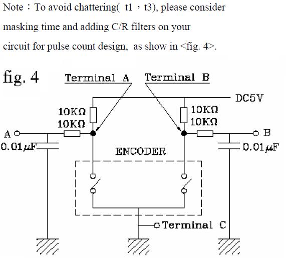
I used both 0.01uF and 0.1uF caps to improve debounce and wired the C pin straight to Vss (only check wiper A and B). This is the recommended circuit by the manufacturer:

Robert


 .
.


 !).
!).

Bookmarks