Amplifier Interference Issue


Closed Thread
Results 1 to 21 of 21

Hybrid View

  1. #1
    Join Date
    Jan 2006
    Location
    Istanbul
    Posts
    1,185


    Did you find this post helpful? Yes | No

    Default

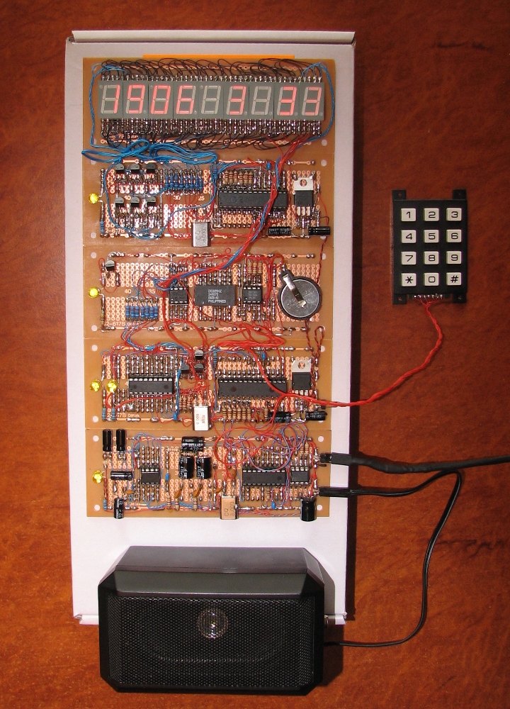
    Attached Images Attached Images  
    "If the Earth were a single state, Istanbul would be its capital." Napoleon Bonaparte

  2. #2
    Join Date
    May 2004
    Location
    NW France
    Posts
    3,648


    Did you find this post helpful? Yes | No

    Default

    Hi, Art

    Nice piece of wrapping ... impressing !!!

    Seriously, I do not see the unforgettable ceramic capacitor ( 0.1 - 0.22µ multilayer ) which ever should be placed CLOSEST as possible to the Pic supply pins ... ( lower and upper right )

    Also, you should try to place the Xtal and its caps on the other side of the pic, close to the pic pins ... ( nice 8 Mhz emitter !!! ... lower right )

    there's lots of noise to catch here ...

    a big reservoir cap ( L.S.R. ) is also a must to place close to the multiplexed LED displays:
    they generate lots of noise ...

    Alain
    ************************************************** ***********************
    Why insist on using 32 Bits when you're not even able to deal with the first 8 ones ??? ehhhhhh ...
    ************************************************** ***********************
    IF there is the word "Problem" in your question ...
    certainly the answer is " RTFM " or " RTFDataSheet " !!!
    *****************************************

  3. #3
    Join Date
    Aug 2003
    Posts
    985


    Did you find this post helpful? Yes | No

    Default

    Thanks

    The 0.1 uF caps are there right next to every pic. They are blue.

    Quote Originally Posted by Acetronics View Post
    Hi, Art

    Nice piece of wrapping ... impressing !!!

    Seriously, I do not see the unforgettable ceramic capacitor ( 0.1 - 0.22µ multilayer ) which ever should be placed CLOSEST as possible to the Pic supply pins ... ( lower and upper right )

    Also, you should try to place the Xtal and its caps on the other side of the pic, close to the pic pins ... ( nice 8 Mhz emitter !!! ... lower right )

    there's lots of noise to catch here ...

    a big reservoir cap ( L.S.R. ) is also a must to place close to the multiplexed LED displays:
    they generate lots of noise ...

    Alain

  4. #4
    Join Date
    Aug 2003
    Posts
    985


    Did you find this post helpful? Yes | No

    Default

    Bah! bit of a nightmare project.

    I think the noise stopped when I was using a capacitor is because I was holding
    it with my fingers.

    I have tried a transistor OR gate to ground the input pin of the amplifier.
    The amplifier is connected to an FM radio circuit, and a pic pin that produces sound.
    The OR gate can receive a busy signal from either the pic or radio circuits
    to make it stop shorting the amplifier input to ground.

  5. #5
    Join Date
    May 2004
    Location
    NW France
    Posts
    3,648


    Did you find this post helpful? Yes | No

    Red face

    Quote Originally Posted by Art View Post
    Thanks

    The 0.1 uF caps are there right next to every pic. They are blue.

    Hi,

    Blue or not ...

    They still are TOO FAR from the pic supply pins ...

    Alain
    ************************************************** ***********************
    Why insist on using 32 Bits when you're not even able to deal with the first 8 ones ??? ehhhhhh ...
    ************************************************** ***********************
    IF there is the word "Problem" in your question ...
    certainly the answer is " RTFM " or " RTFDataSheet " !!!
    *****************************************

  6. #6
    Join Date
    Aug 2003
    Posts
    985


    Did you find this post helpful? Yes | No

    Default

    Quote Originally Posted by Acetronics View Post
    Hi,

    Blue or not ...

    They still are TOO FAR from the pic supply pins ...

    Alain
    You think I'd hear less noise from the amp if I moved the 0.1uF caps closer to each chip?

    I had another idea. What if next time I used a copper clad board of the same
    size underneath the proto PCB, so I could drill one layer down to a ground plane at any location?

Similar Threads

  1. Controlling volume of an amplifier..
    By joseph Degorio in forum Schematics
    Replies: 33
    Last Post: - 17th May 2014, 04:15
  2. Puzzling issue with I2CWRITE to 24LC512
    By aberco in forum General
    Replies: 4
    Last Post: - 22nd August 2008, 17:47
  3. Pic Interference and Power Filter Question
    By Hylan in forum General
    Replies: 3
    Last Post: - 24th January 2008, 07:50
  4. 18F1320 ... Strange Memory
    By Acetronics2 in forum mel PIC BASIC Pro
    Replies: 43
    Last Post: - 9th April 2006, 09:55
  5. Inductive Load Switching and Interference
    By hughgoodbody in forum Off Topic
    Replies: 0
    Last Post: - 23rd December 2005, 17:59

Members who have read this thread : 0

You do not have permission to view the list of names.

Posting Permissions

  • You may not post new threads
  • You may not post replies
  • You may not post attachments
  • You may not edit your posts