"If the Earth were a single state, Istanbul would be its capital." Napoleon Bonaparte
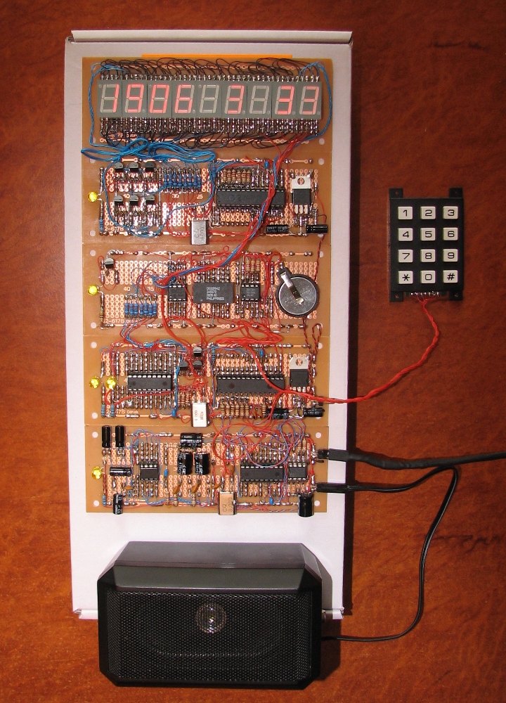
there are 5 PCBs in the project picture, they are just close together.
Each has a gnd and + 5 Volt rail, except the amp which takes power from
whatever power is input before the 7805s, or from + 5 Volts in the case
that I can supply the circuit with regulated 5 Volts like on a desk at home.
All of those ground rails are connected together.
It would have been exactly the same rail if the tracks ran vertical up one big board.
Is there any difference?
When you say "together" do you mean in a spagetti form one after another or in a star form?
The enter of the star is where the power supply (-) should be connected.
All other connections and configurations are creating ground loop currents.
Also if possible use this kind of connection fr the (+) of the other pcb's too. The star topology is very important to minimize interferance. Thena good decoupling locally is also very helpful.
Ioannis
"If the Earth were a single state, Istanbul would be its capital." Napoleon Bonaparte
Hi, Art
Nice piece of wrapping ... impressing !!!
Seriously, I do not see the unforgettable ceramic capacitor ( 0.1 - 0.22µ multilayer ) which ever should be placed CLOSEST as possible to the Pic supply pins ... ( lower and upper right )
Also, you should try to place the Xtal and its caps on the other side of the pic, close to the pic pins ... ( nice 8 Mhz emitter !!! ... lower right )
there's lots of noise to catch here ...
a big reservoir cap ( L.S.R. ) is also a must to place close to the multiplexed LED displays:
they generate lots of noise ...
Alain
************************************************** ***********************
Why insist on using 32 Bits when you're not even able to deal with the first 8 ones ??? ehhhhhh ...
************************************************** ***********************
IF there is the word "Problem" in your question ...
certainly the answer is " RTFM " or " RTFDataSheet " !!!
*****************************************
Bah! bit of a nightmare project.
I think the noise stopped when I was using a capacitor is because I was holding
it with my fingers.
I have tried a transistor OR gate to ground the input pin of the amplifier.
The amplifier is connected to an FM radio circuit, and a pic pin that produces sound.
The OR gate can receive a busy signal from either the pic or radio circuits
to make it stop shorting the amplifier input to ground.
************************************************** ***********************
Why insist on using 32 Bits when you're not even able to deal with the first 8 ones ??? ehhhhhh ...
************************************************** ***********************
IF there is the word "Problem" in your question ...
certainly the answer is " RTFM " or " RTFDataSheet " !!!
*****************************************
Bookmarks