Amplifier Interference Issue


Closed Thread
Results 1 to 21 of 21

Hybrid View

  1. #1
    Join Date
    Aug 2003
    Posts
    985

    Default Amplifier Interference Issue

    Hi Guys,
    I have a few projects where pics make sounds (as do a lot of us I imagine).
    In a few projects I have used a small 1 Watt amplifier to drive a loudspeaker.

    All is good, but I hear a little hum from the amp when it's supposed to be silent.
    If the project has a flashing LED or the like, I then Hear a hum flashing at two different frequencies.
    I assume this is interference from the pic itself.

    A solution I'm thinking of is to leave the amplifier on all the time,
    but to allow the pic to switch on the speaker only while a sound is being played.
    The interference is inaudible while a sound is actually playing.

    My question is.. What is a suitable circuit to achieve this?
    The amplifier chip is a TDA2822M.
    Cheers, Art.

  2. #2
    Join Date
    Jan 2009
    Location
    California, USA
    Posts
    323


    Did you find this post helpful? Yes | No

    Default

    Is the noise coming form the output pin of the PIC and fed to the input of your amp, or is it being coupled in through the power supply?

    If you disconnect and ground the inputs of your amps does it go away?

    If you set the PIC pin that drives it to an input (during the time you're not using it) would that help?

    steve

  3. #3


    Did you find this post helpful? Yes | No

    Default

    You've got a whole list of things to run down...

    Where is your power coming from? A battery, wall-wart, PC? If it's anything other than a battery you need to see how quiet the supply is. Wall-warts are incredibly noisy and unless you take care you are going to get noise. What kind of decoupling do you have on the supply? You're going to need something fat and something skinny. Start with 100uF-470uF electrolytic on the rail. Pair that with a 0.01-0.1uF ceramic (maybe both). Skipping this and you might as well forget it. You can go further and use a series resistor in the supply but start with the caps.

    How is the input connected? AC-couple (use a cap on the input to the amp). Something like a 0.47uF should do it. Then it doesn't matter if the PIC is an output or an input (the cap blocks DC. Regardless if it's an output high or low nothing is showing up at the amp. The only time the amp sees signal is when you are outputing "sound" as an AC waveform). Use a high value resistor to ground on the input of the amp (on the amp side of the cap). Something like a 1M ohm (the data sheet shows a 10K but this is to match the output from a preceeding pre-amp or line level. You don't need that coming from a PIC). This keeps the input at ground unless there is a signal.

    Are your grounds tied together at one point (preferably at the supply)? If you have multiple ground paths then you're going to get into trouble. Tie the supply leads together at the supply. Use a single wire from the output of the PIC to the input cap.

    Looking at the data sheet you should run this in BTL (bridge-tied load) configuration. This uses both amps in the package and gets rid of the big caps on the output (the 470's). This part uses a lot of caps, make sure you are using them. Keep the leads short and if you are using a "plug-strip" protoboard get rid of it and solder the stuff together. Flying leads between components are far better than proto-boards.

    There are amps out there that have an enable pin. You can get one of those and turn the amp on and off as you need. If something is battery powered this saves on power. This only masks the problem however; the hum and noise are still present unless you get rid of it.

    Mike Tripoli

  4. #4
    Join Date
    Aug 2003
    Posts
    985


    Did you find this post helpful? Yes | No

    Default

    Ok, that gives me a lot to think about.
    Unfortunately the protoboard has to stay (this is a one off).
    I am using a plugpack, but the interference sound seems vary according to what the pic/s are doing, so I don't know what that means.
    I don't think i've ever tested this particular project with a battery though,
    so that might be interesting, thanks

    I guess I'll revive this if I run into trouble.

  5. #5
    Join Date
    Aug 2006
    Location
    Look, behind you.
    Posts
    2,818


    Did you find this post helpful? Yes | No

    Default

    Quote Originally Posted by Art View Post
    . . .but the interference sound seems vary according to what the pic/s are doing, so I don't know what that means.
    That could be a variation in leakage across the diode's junction due to changes in load . . . Used to see that a lot in car alternators.
    If you do not believe in MAGIC, Consider how currency has value simply by printing it, and is then traded for real assets.
    .
    Gold is the money of kings, silver is the money of gentlemen, barter is the money of peasants - but debt is the money of slaves
    .
    There simply is no "Happy Spam" If you do it you will disappear from this forum.

  6. #6
    Join Date
    Aug 2003
    Posts
    985


    Did you find this post helpful? Yes | No

    Default

    Is that a rectifier diode in the plugpack power supply ?

    Hey mtripoli,
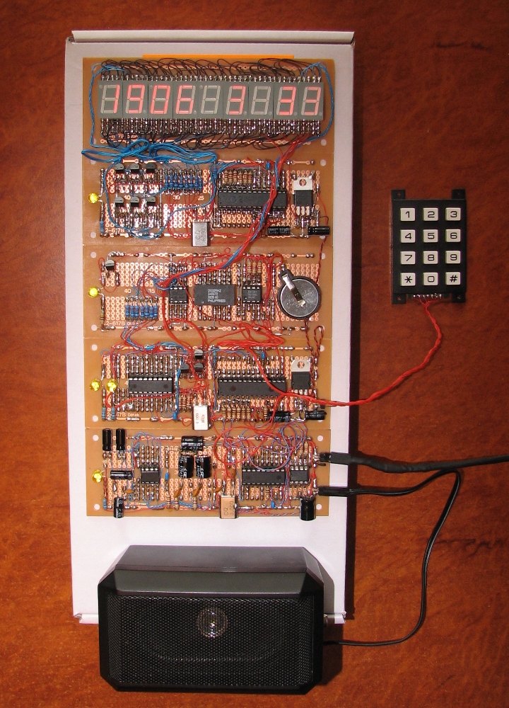
    How would you like to make a PCB for this:


    Give me a bit and I'll whip up a schematic with the transistors the wrong way round
    Nah just kidding

    I'm not actually using the 7805s at the moment because I have a 2 amp 5 Volt regulated wall supply.
    The plugpack is a charger for a Sony PSP, and I would have thought the caps would be in that.

    So it's a talking clock with a display now, but I also want to add an FM radio that I'm making with a Philips FM radio IC tonight.

    There should be some circuit to switch the input of the amplifier chip
    between the pic and the radio chip.
    Should I use signal transistors?
    Last edited by Art; - 3rd March 2010 at 09:38.

Similar Threads

  1. Controlling volume of an amplifier..
    By joseph Degorio in forum Schematics
    Replies: 33
    Last Post: - 17th May 2014, 04:15
  2. Puzzling issue with I2CWRITE to 24LC512
    By aberco in forum General
    Replies: 4
    Last Post: - 22nd August 2008, 17:47
  3. Pic Interference and Power Filter Question
    By Hylan in forum General
    Replies: 3
    Last Post: - 24th January 2008, 07:50
  4. 18F1320 ... Strange Memory
    By Acetronics2 in forum mel PIC BASIC Pro
    Replies: 43
    Last Post: - 9th April 2006, 09:55
  5. Inductive Load Switching and Interference
    By hughgoodbody in forum Off Topic
    Replies: 0
    Last Post: - 23rd December 2005, 17:59

Members who have read this thread : 0

You do not have permission to view the list of names.

Posting Permissions

  • You may not post new threads
  • You may not post replies
  • You may not post attachments
  • You may not edit your posts