


144 LED Game Console
Featuring original recoded clones of two classic games: Snake and Tetris!
Art 2010 -------------------- Note: This is not an official Tetris product.
144 LED Game Console - Bill Of Material
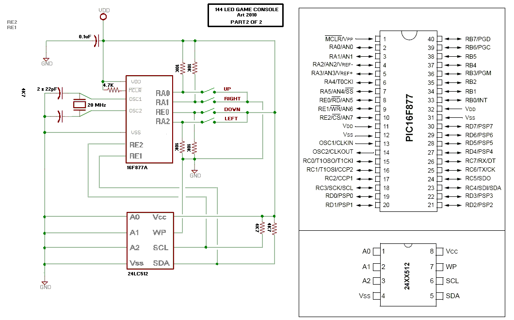
001 x Microchip Pic 16F877 or 16F877A microcontroller
001 x 40 pin DIL socket
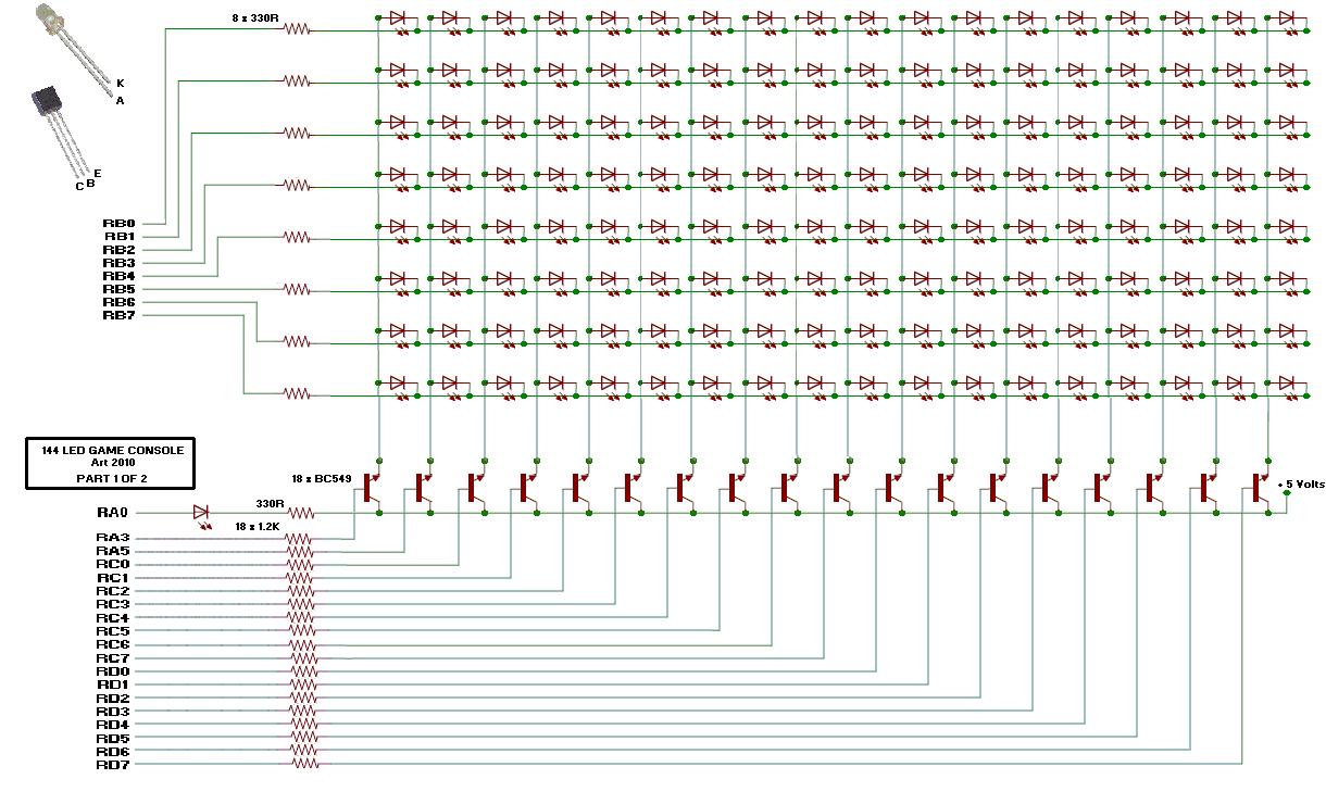
018 x BC549C or similar Transistors
145 x LEDs (144 of one colour, and 1 of another for the power/error indicator)
001 x 20 MHz Crystal
009 x 330R Resistors
018 x 1K2 Resistors
004 x 10K Resistors
001 x 4K7 Resistor
002 x 22pF Disc Ceramic Capacitors
001 x 0.1 uF Monolythic Capacitor
001 x Prototype Printed Circuit Board (display)
001 x Small Prototype Printed Circuit Board (joypad)
004 x Momentary Push Buttons
Display schematic is made from a modified version of a display by B.Morse.
See YouTube Demos of the Games Here:
http://www.freewebs.com/defxev/scroll.htm
Code for the Microcontroller is coming soon!
PS. If someone would like to make a PCB layout, that would be cool
Cheers, Art.


 If you tilt the board 90 degrees the joystick pad (and display) can "rearrange" to the correct orientation?


Bookmarks