Originally Posted by
retepsnikrep

Thanks for the reply. I do plan on doing something with this in due course.
Great confidence I have now ... NOT!
Oh well, more things to do tomorrow I have ....
Tonight, I do this ...
Next year, you may try it.

Code:
DEFINE OSC 8

SPWMpin  var GPIO.5     ' Output Pin for SSPWM
INCLUDE "SSPWM.inc"     ' include the SSPWM module

;----[Constants]------------------------------------------
HPWMfreq        CON 20000
Freq = 2000             ' Set Frequency of SSPWM (word)

;----[Variables]------------------------------------------
HPWMduty        VAR BYTE
LastHPWMduty    VAR BYTE
SSPWMduty       VAR BYTE

;----[Initialize]-----------------------------------------
OSCCON = %01110000      ' 8Mhz
ANSEL = %000011         ' AN0 and AN1 ANALOG
DutyCycle = 10          ' Set Duty Cycle of SSPWM
gosub StartSPWM         ' Start SSPWM @ Freq/DutyCycle
HPWM 1, 127, HPWMfreq   ' Start 20Khz PWM @ 50%

;----[Main Program Loop]---------------------------------
Main:
    ADCIN 0, HPWMduty
    ADCIN 1, SSPWMduty

    IF HPWMDuty != LastHPWMduty THEN
        LastHPWMduty = HPWMDuty
        HPWM 1, HPWMDuty, HPWMfreq
    ENDIF


    DutyCycle = SSPWMduty*80/256+10  ' scale SSPWM dutycycle
    gosub SetSPWM                    ' Change SSPWM DutyCycle
GOTO Main
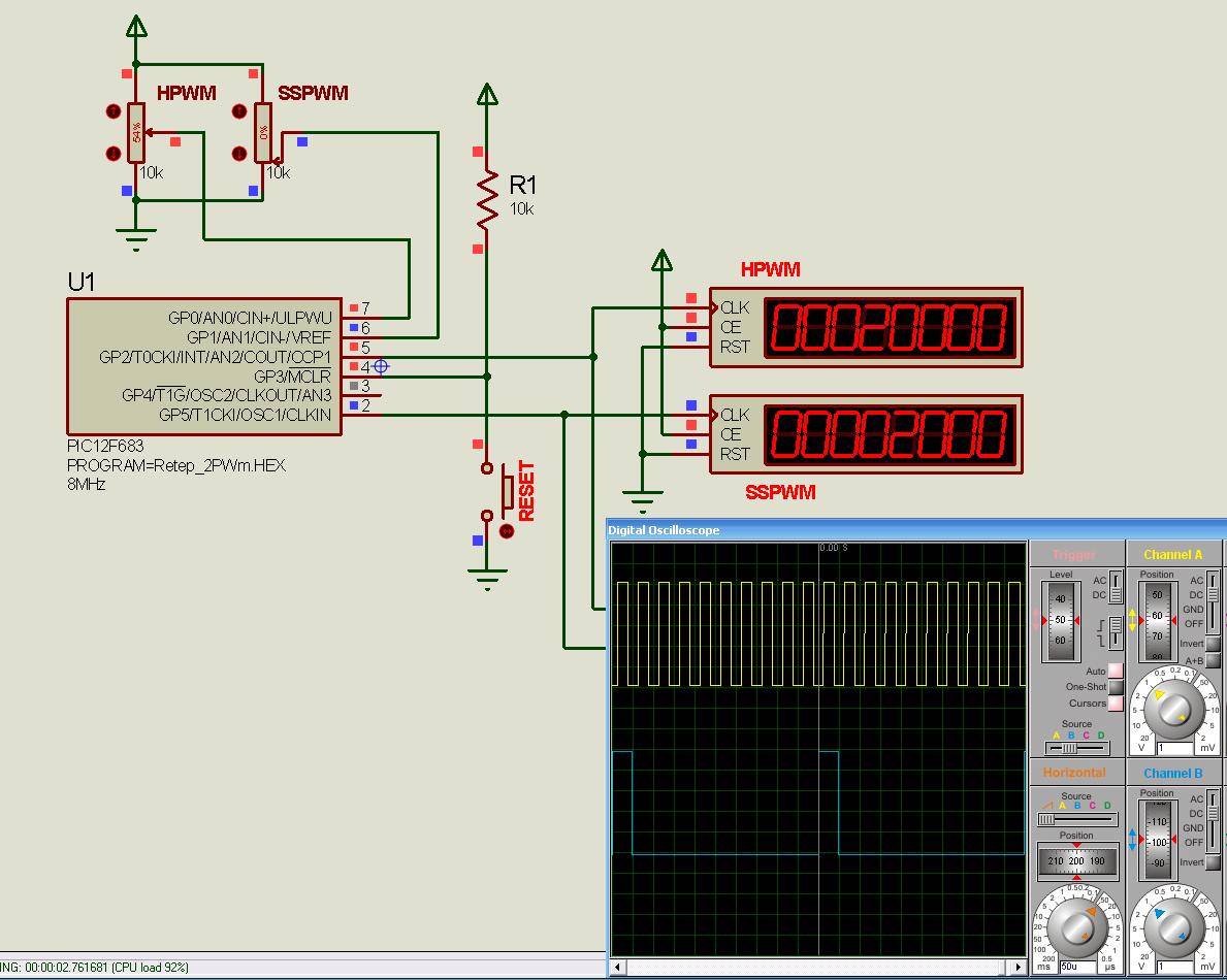
Dutycycle of the 2Khz is 10% in the image.
Both dutycycles are adjustable from the pots, and works from 10% to 90%, (0 to 100% for the HPWM).
Don't forget to comment the wsave vars not used by the 683 in the .inc file.
Happy Holidays.


 ) - I need single channel SPWM fixed 95% duty with 85 Hz from 12F683 to drive LEDs (and perhaps extend their life)?


Bookmarks