Code:
'
'
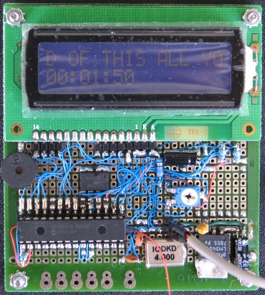
' Battery Monitor 2009
' Art
'
DEFINE INTHAND ROLLOVER
wsave var BYTE $020 SYSTEM
wsave1 var BYTE $0a0 SYSTEM
wsave2 var BYTE $120 SYSTEM
wsave3 var BYTE $1a0 SYSTEM
ssave var BYTE BANK0 SYSTEM
psave var BYTE BANK0 SYSTEM
i_hour var BYTE
i_minu var BYTE
i_sec var BYTE
i_tic var BYTE
GOTO AFTERINT 'Jump past interrupthandler
ASM
ROLLOVER
; interrupcode follows here
movlw 0x58
movwf TMR1L
movlw 0x9e ;restart timer from ffff - 9e58 => 5Hz if using 4MHz
movwf TMR1H
decfsz _i_tic,f
goto slutint
incf _i_sec,f
movlw 5 ;5 = 1Hz if using 4MHz (change to 10 for 8MHz and so on)
movwf _i_tic
movf _i_sec,w
sublw 60
btfss STATUS,Z ;check for 60 sec
goto slutint ;no
clrf _i_sec ;yes
incf _i_minu,f
movf _i_minu,w
sublw 60
btfss STATUS,Z ;check for 60 minutes
goto slutint ;no
clrf _i_minu ;yes
incf _i_hour
movf _i_hour,w
sublw 24
btfss STATUS,Z ;check for 24 hours
goto slutint ;no
clrf _i_hour ;yes
slutint
bcf PIR1,0 ;zero tmr1 interrupt flag
;end of interruptcode
; restorecode follows here
movf psave,w ;restore
movwf PCLATH
swapf ssave,w
movwf STATUS
swapf wsave,f
swapf wsave,w
retfie
ENDASM
AFTERINT:
INTCON = %00000000 'all interrupts off
PIR1 = %00000000 'zero tmr1 interrupt flag
PIE1 = %00000001 'enable timer1 interrupt
TMR1L = $58
TMR1H = $9e
i_hour = 0
i_minu = 0
i_sec = 0
i_tic = 5 'this value should be the same as the value of line 8 in the ISR
T1CON = %00110001 'timer1 on, prescaler=1/8
INTCON = %11000000 'interrupt on
@ DEVICE LVP_OFF,BOD_OFF,LP_OSC 'set device configuration
'
TRISA = %111111 'Set porta to all imputs
ADCON1 = %10001001 'configure ADC port pins
ADCON0 = 0 '
'
DEFINE LCD_DREG PORTB 'set LCD display congiguration
DEFINE LCD_DBIT 4 '
DEFINE LCD_RSREG PORTB '
DEFINE LCD_RSBIT 1 '
DEFINE LCD_EREG PORTB '
DEFINE LCD_EBIT 0 '
DEFINE LCD_BITS 4 '
DEFINE LCD_LINES 2 '
DEFINE LCD_COMMANDUS 2000 '
DEFINE LCD_DATAUS 50 '
'
DEFINE ADC_BITS 10 'set ADC configuration
DEFINE ADC_CLOCK 0 '
DEFINE ADC_SAMPLEUS 50 '
'
WORK0 var word '
LAST0 var byte 'padding buffers
LAST1 var byte '
LAST2 var byte '
LAST3 var byte '
LAST4 var byte '
LAST5 var byte 'padding buffers
LAST6 var byte '
LAST7 var byte '
LAST8 var byte '
LAST9 var byte '
'
DAT0 var byte 'define variables
DAT1 var byte '
DAT2 var byte '
ADDR var byte 'I2C variables
CONT var byte '
CNT0 var byte 'counters
CNT1 var byte '
CNT2 var byte '
CNT3 var byte '
SNDF var bit 'sound flag
CHAR var byte 'LCD character
scomp var byte 'second compare
TENS var byte '
UNTS var byte '
DECS var byte '
'
'
DAT0 = 0 : DAT1 = 0 : DAT2 = 0 'reset variables to zero
ADDR = 0 : CONT = 0 : CNT0 = 0 '
CNT1 = 0 : CNT2 = 0 : CNT3 = 0 '
SNDF = 0 : CHAR = 0 '
LAST0 = 0 : LAST1 = 0 : LAST2 = 0 '
LAST3 = 0 : LAST4 = 0 : WORK0 = 0 '
LAST5 = 0 : LAST6 = 0 : LAST7 = 0 '
LAST8 = 0 : LAST9 = 0 '
'
PAUSE 1000 'LCD startup time
LCDOUT $FE,1 'clear LCD
'
CONT = %10100000 'set I2C control variable - %1010bbb0
'
'FOR CNT1 = 0 TO 255 'write loop
'ADDR = CNT1 '
'I2CWRITE PORTC.4,PORTC.5,CONT,ADDR,[ADDR] 'test write
'PAUSE 10 '
'NEXT CNT1 '
'CNT1 = 0 '
'
LCDOUT $FE,$40,128,138,138,128,145,145,142,128 'set LCD custom smiley character
'
SOUND PORTB.2,[20,10,70,10] 'make startup sound
'
'
cycle:
'
LCDOUT $FE,2 'LCD cursor return home
CNT3 = CNT2 'store current scroll position
FOR CNT1 = 0 TO 15 '
READ CNT2,CHAR 'read character from on-chip EEPROM
LCDOUT CHAR 'print character
CNT2 = CNT2 + 1 '
IF CNT2 > 254 THEN CNT2 = 0 '
NEXT CNT1 '
CNT2 = CNT3 'restore scroll position
'
CNT2 = CNT2 + 1 'advance scroll position
IF CNT2 > 254 THEN CNT2 = 0 '
'
'
scomp = 0
IF scomp = 0 THEN
'
ADCIN 0,DAT0 'read ADC to variable
'ADDR = CNT0 'set EEPROM address
'I2CREAD PORTC.4,PORTC.5,CONT,ADDR,[DAT1] 'read from EEPROM
LCDOUT $FE,$C0 'second line
IF i_hour < 10 THEN LCDOUT "0" '
LCDOUT #i_hour 'print variables
LCDOUT ":" '
IF i_minu < 10 THEN LCDOUT "0" '
LCDOUT #i_minu '
LCDOUT ":" '
IF i_sec < 10 THEN LCDOUT "0" '
LCDOUT #i_sec '
'
LAST9 = LAST8 '
LAST8 = LAST7 '
LAST7 = LAST6 '
LAST6 = LAST5 '
LAST5 = LAST4 '
LAST4 = LAST3 '
LAST3 = LAST2 '
LAST2 = LAST1 '
LAST1 = LAST0 '
LAST0 = DAT0 '
'
WORK0 = LAST0 + LAST1 + LAST2 + LAST3 + LAST4 'calculate mean average
WORK0 = WORK0 + LAST5 + LAST6 + LAST7 + LAST8 '
WORK0 = WORK0 + LAST9 '
WORK0 = WORK0 / 10 '
DAT0 = WORK0 '
'
TENS = DAT0 DIG 2 'get separate digits
UNTS = DAT0 DIG 1 '
DECS = DAT0 DIG 0 '
'
LCDOUT " " 'print Voltage
IF DAT0 < 100 THEN '
LCDOUT " " '
ELSE '
LCDOUT #TENS '
ENDIF '
LCDOUT #UNTS '
LCDOUT "." '
LCDOUT #DECS '
LCDOUT "V" '
IF DAT0 = 0 THEN
SOUND PORTB.2,[100,10,50,10] 'sound alarm for zero Volts
PAUSE 150 '
ELSE '
PAUSE 300 '
ENDIF '
SNDF = 1 'set sound flag
CNT0 = CNT0 + 1 'increment counter
ENDIF '
'
IF SNDF = 0 THEN
PAUSE 300 'delay
ELSE
SNDF = 0
ENDIF
'
goto cycle
'


Bookmarks