Any tips for 4-layer boards?


Closed Thread
Results 1 to 31 of 31

Hybrid View

  1. #1
    Join Date
    Jul 2003
    Posts
    2,358


    Did you find this post helpful? Yes | No

    Default

    Here's the HPWM code I use to drive Contrast...

    Code:
    SetLCDContrast:
    	DataA=Contrast*40
    	HPWM 2,DataA,1000
    	Return
    DataA is a byte variable. Contrast is a User software selectable value between 1 and 5. The factory default is 2.

    A Capacitor is a waste of real-estate. Your eye can't distinguish 30Hz (TV picture frame rate) let alone 1kHz as used above... your LCD probably can't switch that fast either. How fast is your LCD monitor... 3mS? - mine's closer to 9.

    As always, try it on a breadboard with your chosen LCD before you commit to PCB... I've used it sucessfully on dozens of different PowerTip and Tri-T LCD's without problems.

    If you have a couple of PWM channels, use the other one for the Backlight... same code... do a Search for Easy Backlight.

  2. #2
    Join Date
    Jan 2009
    Location
    California, USA
    Posts
    323


    Did you find this post helpful? Yes | No

    Default

    Thank you Melanie, that's great!

    I'll give it a try as soon as I get a chance. It saves some expense, and a bit of real estate, and 1 PIC pin compared to the digital pot method. Very nice!

    I'm already using the other PWM channel to drive a MOSFET for the backlight. I figured out how to do that several projects ago.

    I'll give your circuit a test to make sure it works with my LCD before I commit to a run of boards, but it sounds like a very happy thing for my project.

    Thanks ever so much for your help!


    steve

  3. #3
    Join Date
    Jan 2009
    Location
    California, USA
    Posts
    323


    Did you find this post helpful? Yes | No

    Default

    Well I just tried Melanie's "Easy Contrast" circuit and it works great!
    I tried with and without a filter cap and there's no visible difference.
    I ended up using 2K and 1K resistors because I had some laying within arms reach and it gives good control.

    That's cheaper and uses less real estate than a trimpot, and it gives the user control that I was going to use a digital pot to achieve. With only 2 resistors.

    Most Excellent! Thanks Melanie!


    steve

  4. #4
    Join Date
    Jan 2009
    Location
    California, USA
    Posts
    323


    Did you find this post helpful? Yes | No

    Default I got it all on 2-layers!

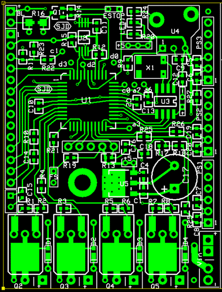
    Well, I shuffled a bunch of stuff around, made a few circuit changes, and presto!
    It all fits on 2-layers now.

    5 IC's
    19 Capacitors
    28 Resistors
    5 Transistors
    4 Diodes
    1 Crystal,
    1 LED
    + connectors and wires to the outside world.... power supply, sensors, LCD, etc.

    All on a board that's about 2.5" high and less than 2" wide.

    Thanks to everyone that provided suggestions and insight. Much appreciated.


    steve


  5. #5
    Join Date
    Nov 2003
    Location
    Greece
    Posts
    4,132


    Did you find this post helpful? Yes | No

    Default

    Thats great news! Now, how are you going to solder components?

    Ioannis

  6. #6
    Join Date
    Jan 2009
    Location
    California, USA
    Posts
    323


    Did you find this post helpful? Yes | No

    Default

    Quote Originally Posted by Ioannis View Post
    Thats great news! Now, how are you going to solder components?
    I've got some good stout radiator solder and a propane torch.

    Actually, I'm modestly well setup to do SMD boards. I have a homemade reflow oven (modified toaster oven) and a cheap hot air rework station.
    I've done quite a few small SMD boards but nothing quite as tight as the current one.

    Here's a basic PIC controller board with RTC and EEPROM on board. Various versions of it lounge around on my bench, being test beds for assorted projects...


    Since this latest board has up to 63 parts on less than 5 square inches, I'll definitely cough up the extra $$ to have silkscreen and soldermask on this one.

    I'm glad it all went on 2 layers. I was willing to go to 4, but cheaper is better...


    steve

  7. #7


    Did you find this post helpful? Yes | No

    Default What does it do?

    Outside of reading temperatures, that is? Just seems like a pretty beefy processor to read/display temperatures, so am merely curious.

Similar Threads

  1. Labeling Circuit Boards
    By Atom058 in forum General
    Replies: 7
    Last Post: - 1st August 2008, 15:43
  2. making small boards
    By fowardbias in forum Off Topic
    Replies: 4
    Last Post: - 15th April 2008, 08:58
  3. Replies: 8
    Last Post: - 5th January 2007, 05:10

Members who have read this thread : 0

You do not have permission to view the list of names.

Posting Permissions

  • You may not post new threads
  • You may not post replies
  • You may not post attachments
  • You may not edit your posts