PIC 16f877 A/D conversion Allegro ACS712


Closed Thread
Results 1 to 33 of 33

Hybrid View

  1. #1
    Join Date
    Dec 2005
    Posts
    1,073


    Did you find this post helpful? Yes | No

    Default

    Quote Originally Posted by DavyJones View Post
    If I could get a reading form the ACS712 at the top/bottom of each wave then it could be done but then that is what the RMS to DC is going to do for me give me a nice straight DC line.
    You are still making an unwarranted assumption that you have a sine wave. Darrell is suggesting the RMS chip and I suggested looking at the output of the Allegro chip with an oscilloscope (to see the waveform) because we don't think you have a sine wave. 0.707 x the peak will work with a sine wave and averaging ALL of the readings will work with any waveform (if the readings can be taken fast enough to get a good sampling of the wave form).

    There are at least three ways to do this with non-sinusoidal waveforms. See the web page I referenced earlier (via email)...
    I vaguely recalled a somewhat similar thread - it took me a while to find it.
    Last edited by dhouston; - 4th August 2009 at 16:41.

  2. #2
    Join Date
    Jan 2008
    Location
    Pennsylvania
    Posts
    113


    Did you find this post helpful? Yes | No

    Default Agreed

    Dave,
    I can see were I made it sound like I thought I still have a pure sine wave thats not what I meant. What I was actually trying to say was what you just stated that because it was not a pure sine wave if I took thousands of readings and averaged those it would work.

    I'm looking at the document I saw that link in the email but it came acrossed somewhat broken I did not get the entire link as a complete link in the email.

    Thanks
    David

  3. #3
    Join Date
    Dec 2005
    Posts
    1,073


    Did you find this post helpful? Yes | No

    Default

    Quote Originally Posted by DavyJones View Post
    I can see were I made it sound like I thought I still have a pure sine wave thats not what I meant. What I was actually trying to say was what you just stated that because it was not a pure sine wave if I took thousands of readings and averaged those it would work.
    It's a bit more complicated - it requires some complex math. See Digital True RMS Converters on page 3 of the referenced pdf.

    If you look at the waveform and see it is more or less sinusoidal, then 0.707 x the peak output of the Allegro should get you close enough for what you're trying to do.

  4. #4
    Join Date
    Jan 2008
    Location
    Pennsylvania
    Posts
    113


    Did you find this post helpful? Yes | No

    Default I have some homework

    Dave, Thanks I appreciate all you and Darrel are teaching me and not getting to stressed with me while I try to learn this. I'm going to work on capturing the wave this evening and take a look at what I see. I do have the components that Darrel suggested on order as well I want to hook those up in any event to help me understand. Things are so much easier when the device is DC like they were with the pressure transducer.

    thanks again
    David

  5. #5
    Join Date
    Apr 2009
    Location
    Pittsburgh, PA
    Posts
    17


    Did you find this post helpful? Yes | No

    Default Oops

    I work with someone called Darrin and Darryl and I always get them mixed up. Sorry for getting your name wrong Darrel - lord knows I've seen it often enough .

  6. #6
    Join Date
    Mar 2011
    Location
    Bangkok Thailand
    Posts
    16


    Did you find this post helpful? Yes | No

    Default Re: PIC 16f690 Allegro ACS712 + -30Amp

    Is this the way to get negative reading? i am new to this, so sorry if i mixed it up.

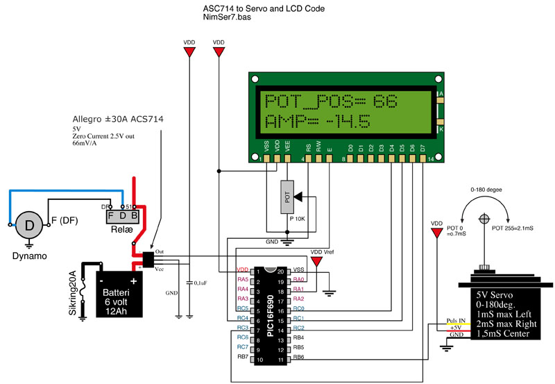
    I use Allegro ACS714 but with a PIF16F690 with A/D set to 8bit, should not be any difference.

    It works and can read +30Amp to -30Amp.

    The problem is that i use 0V and 5V as reference. I cant figure out to get 0.52V to read 0 and 4.48V to read 255? Is it a math problem or must i add an external ref?

    The ACS gives 66mV/A:
    Amp Vin Bit
    +30A 4.480 255
    +10A 3.160
    +1A 2.566
    0A 2.500 127
    -1A 2,434
    -10A 1.840
    -30A 0.520 0

    See CODE below and attached DRAWING

    Name:  ASC714 to LCD.jpg
Views: 40376
Size:  87.8 KB
    Code:
    'Define OSC and ADC
    DEFINE OSC 4             ' Set internal Oschillator to 4Mhz
    DEFINE    ADC_BITS 8       ' Set number of bits in result
    DEFINE    ADC_CLOCK 2      ' Set clock source (3=rc)
    DEFINE    ADC_SAMPLEUS 50  ' Set sampling time in uS
    ' Define LCD pins
    Define LCD_DREG  PORTC   'LCD data port
    Define LCD_DBIT  0       'LCD data starting bit 0 or 4
    Define LCD_RSREG PORTC   'LCD register select port
    Define LCD_RSBIT 4       'LCD register select bit
    Define LCD_EREG  PORTC   'LCD enable port
    Define LCD_EBIT  5       'LCD enable bit
     
     
    TRISA = %00001001                         ' RA0 = A/D input
    ADCON1.7 = 0                                  ' RA.1 = +Vref, Set PORTA analog and left justify result
    PORTb.6  =0                                     ' Prepare RB0 for high-going pulseout
    
    ANSEL = %00000101                         ' Set PORTA.2 analog, rest digital
    ANSELH = %00000000
    
    ' Variables
    outpuls VAR WORD                           ' Variable for the calculated puls out in mS
    POT_POS VAR BYTE                          ' Potentiometer position CC=0, CCW=255
    amp var word                                   ' Ampere 30A-0-30A (0-127-255)
                                     
    Pause 500                                 ' Wait for LCD to start
    
    MainLoop:                                 ' The Loop start here!
    ADCIN 0,POT_POS                           ' Read A/D channel 0 to variable SVO_POS
    
    'Check if negative or positive Ampere
    IF POT_POS=>127 then
    amp=(235 * (POT_POS-127))
    else
    amp=(235 * (128-POT_POS))
    endif
    
    Lcdout $fe, 1, "POT_POS= ", #POT_POS      ' Display POT Valu between 0-255 on line 1
    
    ' Check if negtive or positive Ampere, only for - minus sign on LCD display
    IF POT_POS=>127 then
    LCDOut $fe,$C0, "AMP= ",DEC (amp/1000),".", DEC1 amp' Display +Amp on line 2
    else
    LCDOut $fe,$C0, "AMP= -",DEC (amp/1000),".", DEC1 amp' Display -Amp on line 2
    endif 
    
    PAUSE 20                                  ' Constant 20mS pulses(low) between outpuls
    GOTO MainLoop                             ' Forever
    End
    

    Last edited by Archangel; - 7th June 2011 at 18:21. Reason: non;add code tags

Similar Threads

  1. A/D conversion with PIC18F67J50
    By ScaleRobotics in forum mel PIC BASIC Pro
    Replies: 9
    Last Post: - 8th May 2009, 01:48
  2. A/D conversion problem in 18F2520, 2523, 2550 etc.
    By selimkara in forum mel PIC BASIC Pro
    Replies: 9
    Last Post: - 10th March 2008, 16:26
  3. 16f877 A/D help
    By 3adam in forum mel PIC BASIC Pro
    Replies: 1
    Last Post: - 25th January 2008, 04:06
  4. A/D converter fails?
    By egberttheone in forum mel PIC BASIC Pro
    Replies: 14
    Last Post: - 13th February 2006, 18:57
  5. Strange A/D conversion...
    By Christos_K in forum mel PIC BASIC Pro
    Replies: 4
    Last Post: - 5th June 2005, 01:35

Members who have read this thread : 0

You do not have permission to view the list of names.

Tags for this Thread

Posting Permissions

  • You may not post new threads
  • You may not post replies
  • You may not post attachments
  • You may not edit your posts