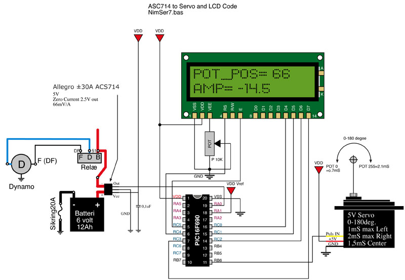
PIC 16f877 A/D conversion Allegro ACS712


Closed Thread
Results 1 to 33 of 33

Hybrid View

  1. #1
    Join Date
    Dec 2005
    Posts
    1,073


    Did you find this post helpful? Yes | No

    Default

    Quote Originally Posted by Darrel Taylor View Post
    If you'll be primarily measuring motor currents, the wave forms will NOT be sine, and .707 will not even come close. In that case, there is only one way to go.

    Run the signal from the current sensor into an R-M-S converter. Don't bother trying to do it in software. I like the LTC1966, but it's a really tiny chip and isn't great for hobby use cause they're too hard to solder.

    There are several other chips available that do the same thing. But for sure you will need an R-M-S (Root Mean Square) reading for any inductive loads.
    <br>
    You can also take many readings (~100 x the frequency or 6000Hz) and average them but I don't think a PIC can do this fast enough for accuracy. This is how digital wattmeters work.

    If an oscilloscope is not available, it might be possible to get an idea of the waveform using a PC or laptop with a LineIn port for the soundcard. The sampling rate should be adequate unless there are sharp spikes. Since the Allegro output is 0-5V, you can use the same technique I use for IR & RF. See...

  2. #2
    Join Date
    Nov 2003
    Location
    Wellton, U.S.A.
    Posts
    5,924


    Did you find this post helpful? Yes | No

    Default

    Not knowing more about the project a simple current transformer might be good enough. You would still need to calibrate it though.

    There are pros and cons to every option, but CTs are good enough for power companies to sell with...

    Let us know which way you want to go.
    Dave
    Always wear safety glasses while programming.

  3. #3
    Join Date
    Jan 2008
    Location
    Pennsylvania
    Posts
    113


    Did you find this post helpful? Yes | No

    Default Good notes and advice as usual.

    Darryl, Your right I should have mentioned that I was trying to measure an AC current right off the bat my mistake.

    So I've got a couple differnt methods and since I want to learn I'm looking at both of these and am leaning more towards the LTC1966.

    Dave no I did not forget you and I have been taking many samples in my code but that does not seem to be working well for me but I do like your example of how to read this with the line in on the sound card and kind of simulate having an oscilliscope that is pretty cool and I am going to be doing that this evening.

    So to the RMS to DC converter. I'm reading the datasheet for the LTC1966 on it's functionality it sounds like as you said run the output of the 712 through and it is going to give me the DC voltage proportionate to the amps that I am trying to read on the pic correct? I'm going to get one and try it out so I can see this for myself.

    Thanks
    David

  4. #4
    Join Date
    Jul 2003
    Location
    Colorado Springs
    Posts
    4,959


    Did you find this post helpful? Yes | No

    Default

    Quote Originally Posted by DavyJones View Post
    I'm going to get one and try it out so I can see this for myself.
    Then get yourself some of the adapters shown below.

    The other picture is a 3-phase current sense board a did for a customer. You can see how small they are. They don't come in any larger packages.

    I was using current transformers instead of hall-effect sensors, but the idea (and RMS requirement) are the same for either type.

    I also had to use a TLV324 op-amp (not shown) to bring it up to levels the PIC could read accurately.
    Attached Images Attached Images   
    DT

  5. #5
    Join Date
    Jan 2008
    Location
    Pennsylvania
    Posts
    113


    Did you find this post helpful? Yes | No

    Default A few more thoughts... That is small

    Yes that package is pretty small... I've been thinking as Mr. Houston pointed out this is what I was initially doing, taking many readings, I realize that because the reading from the ACS712 is going to go along with the sine wave and at any given point in time it could give me a reading anywhere along the wave I'd been taking hundreds of samples and keeping track of the MAX. then after a couple of seconds display this value. I just got an email from Allegro and they pointed out when reading for AC current that the + reading will be 2.5V to 4.5V and the minus side reading will be from .5V to 2.5V Could I not keep track of the MIN as well since the reading will never go negative and add that into my equation averageing the min and max? Where a reading of 169 on the + side of the scale would be a 94 on the minus side of the scale right? If I grab enough of these readings....

    Is this completely wrong to go this route? It seems like it has been working. According to the franklin motor company and my clamp meter it seems like I was really close but my math, in particuliar, my multiplier thats why I started this thread in the first place. It's not imperative that this be a real time reading as long as I can get a reading every couple of seconds then for this application it is going to be fine. What I am doing is basically monitoring the current the submersible pumps are drawing and when the well runs dry the current drops about 1 to 2 amps and when I sense this I can shut the pump down.

    David

  6. #6
    Join Date
    Jul 2003
    Location
    Colorado Springs
    Posts
    4,959


    Did you find this post helpful? Yes | No

    Default

    Nope, can't go that route.

    You ARE measuring currents from inductive loads (submersible pumps).

    So you have to get an RMS reading.
    You would be surprised just how far off the numbers will be. >100%

    I know this too well, because I went down that same road my first time too.
    It was horrible.
    Down right embarrassing actually, since the customer saw it too.
    <br>
    DT

  7. #7
    Join Date
    Jan 2008
    Location
    Pennsylvania
    Posts
    113


    Did you find this post helpful? Yes | No

    Default I trust your experience.

    Quote Originally Posted by Darrel Taylor View Post
    Nope, can't go that route.

    You ARE measuring currents from inductive loads (submersible pumps).

    So you have to get an RMS reading.
    You would be surprised just how far off the numbers will be. >100%

    I know this too well, because I went down that same road my first time too.
    It was horrible.
    Down right embarrassing actually, since the customer saw it too.
    <br>
    I trust you.

    I just wanted to double check myself. I am just playing around now with the min/max on an 85w bulb and just this 85w bulb gives me a bad reading. I get for MAX 132 and MIN is 124 so it's a little off if I run this through the calculation you provided me I get
    (132 - 127 ) * 196 / 66 = 1.48
    (127 - 124 ) * 196 / 66 = .89
    Even avergaing these 2 I come up with 1.18 that is that is double what the clamp meter is telling me is .66 which I tend to believe now because since it truly should be .7 the fact the clamp is telling me .66 and how can I really tell if this bulb is putting off truly 85w.

    Here is something I am seeing that is strange. If I plug the 1600w hairdryer that has 2 settings I get 2 readings as you would expect on low I get 152 MAX and 103 MIN then for the high setting I get 179 MAX and 76 MIN but when I plug in the 10 amp hot air gun which also has 2 settings when I set it on low I get 172 MAX and 127 MIN with the reading I get from the hair dryer I would have expected the min reading on the hot air gun to go to 82 that is goofy why would the hot air gun get such a different result then the hair dryer?

    The LTC is on it's way I found those at digikey looking for the little board for it now. Also getting the TLV324 would it be to much trouble to get a look at how you wired that up with both components to the pic?
    Thanks
    David

  8. #8
    Join Date
    Jun 2011
    Posts
    25


    Did you find this post helpful? Yes | No

    Default Re: PIC 16f877 A/D conversion Allegro ACS712

    Hello Darrel,
    I know the topic is old , but i need help as i am new to analog. Will you be so kind to post the schematic, mostly i am looking at the use of the TLV324. I do not have a clue about op amp, and if i do not find a solution fast to our plant, my boss will send me fishing and get somebody else to replace me. In my case is simpler than the post. I have a machine with 100 heaters, and i would like to use acs712 to detect any burned out heaters, meaning 0 amps. Also i can leave with detecting any heater which is less than one amp. What i want to achieve is to have an optocoupler for each output of ltc1966, and if the current is over or equal with 1 amps to turn the opto ON. the opto will feed a digital input to my micro. If it is simpler i am happy with 0 amps too. what ever it is simpler, no need for calibration, and less components to adjust .
    If you would like you can also write me at [email protected]
    As the issue stands right now, i am in the hot water because i have 10 days to implement a solution.The maximum current on the heaters (110 VAC) it is 4.5 amps ac.
    Thank you

Similar Threads

  1. A/D conversion with PIC18F67J50
    By ScaleRobotics in forum mel PIC BASIC Pro
    Replies: 9
    Last Post: - 8th May 2009, 01:48
  2. A/D conversion problem in 18F2520, 2523, 2550 etc.
    By selimkara in forum mel PIC BASIC Pro
    Replies: 9
    Last Post: - 10th March 2008, 16:26
  3. 16f877 A/D help
    By 3adam in forum mel PIC BASIC Pro
    Replies: 1
    Last Post: - 25th January 2008, 04:06
  4. A/D converter fails?
    By egberttheone in forum mel PIC BASIC Pro
    Replies: 14
    Last Post: - 13th February 2006, 18:57
  5. Strange A/D conversion...
    By Christos_K in forum mel PIC BASIC Pro
    Replies: 4
    Last Post: - 5th June 2005, 01:35

Members who have read this thread : 0

You do not have permission to view the list of names.

Tags for this Thread

Posting Permissions

  • You may not post new threads
  • You may not post replies
  • You may not post attachments
  • You may not edit your posts