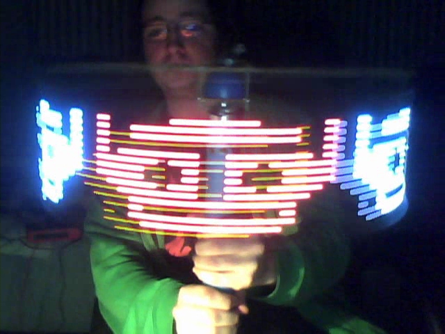
Since no response for a while maybe i can help a little.
The logic behind ANY stable propeller clock is that you need to generate a burst of "led lines" of a specific delay time each so that they fill a full rotation and that the beginning of the burst to always begin in the same position (sync).
Sound like "I already know that", but now to the analysis part:
-First, the sync pulse: If your motor has a tachometer, like a pc fan there you go!. Another forms of syncing are a small value high watt resistor in series with your motor and make a current to voltage rotation detector (only works in some motors), or what most people use, a strong magnet with a hall efect switch or reed switch.
The important thing is to get a stable switching on every turn (no switching loss, no oscillation in position).
-Second, the rotor: The motor has to be big enough to handle the weight of your circuit and everything else at a frequency of 50-100hz (the faster the better). That make a really nice component centrifuge so be careful with mounting stuff (already blown a full propeller right to my face) balance the weight proportional at each side. For getting power to the circuit in the rotor, there are a lot of techniques, you will have to do some research there. The usual way is to just run it from batteries, another way is to use a brushed contact switch of some kind and good pair of capacitors and regulator to avoid any glitches in the contacts
-Then you need your leds: starting in monochrome and with 8 leds directly to the pic is a good way to learn, if you like color or more than 16 leds, its better to use some kind of led controller or serial to parallel latch (74HC595 is my way to go). Color toning is preformed by PWM BUT in a high frequency (at least: Fpwm=20*RPM) and it uses really huge data bandwidths.
In the programming part, your first priority is to poll the sync pulse, when the sync pulse is detected, run the loop of (N-lines) led busts with a small delay each. How calculate the delay, It should be (Delay for each line = Time between last 2 syncs / Nș Lines) With that formula you keep adjusting time according to the last rotational period, that way even if your motor drifts in speed you get a static image.
How to get the time between the 2 syncs is trickier but the most simple way is to count how many lines you have showed and if a sync comes up and you haven't finished all the lines, compensate subtracting time from the delay. On the other hand if you finished your lines and the sync pulse doesn't appear, keep counting blank lines and compensate adding to the delay
For dynamic text, just make a character lookup table and burst from there loading an array sequentially, for the clock part TMR0 interrupt comes to my mind
Hope it helps, learning a little of darrel interrupts in TMR1 (delay) and on PORTBINT(sync) makes things work a little faster an responsive.

"If at first doesn't work, kicking it wont help either"


Bookmarks