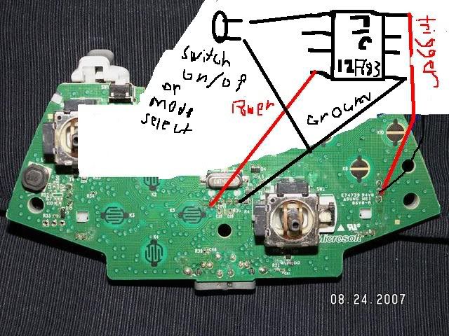
New project help rapidfire on 12f683


Closed Thread
Results 1 to 28 of 28

Hybrid View

  1. #1
    Join Date
    Jul 2003
    Location
    Colorado Springs
    Posts
    4,959


    Did you find this post helpful? Yes | No

    Default

    I've been working on an NKK display in another thread for what seems like a week (3 days). So I hadn't been paying much attention to this one.

    After a quick review, the problem I see is that there are a lot of buttons on the 360 controller. It's most likely that the buttons are "Multiplexed".

    In the PDF of the original project, it shows an input FROM the button, and an output TO the button. So apparently the pulses can only be put out when that button gets scanned.

    This will be more difficult than just toggling a pin 3 times.

    Do you have an oscillicope to verify if they're scanned or not?
    <br>
    DT

  2. #2
    Join Date
    Dec 2008
    Posts
    24


    Did you find this post helpful? Yes | No

    Default

    Quote Originally Posted by Darrel Taylor View Post
    I've been working on an NKK display in another thread for what seems like a week (3 days). So I hadn't been paying much attention to this one.

    After a quick review, the problem I see is that there are a lot of buttons on the 360 controller. It's most likely that the buttons are "Multiplexed".

    In the PDF of the original project, it shows an input FROM the button, and an output TO the button. So apparently the pulses can only be put out when that button gets scanned.

    This will be more difficult than just toggling a pin 3 times.

    Do you have an oscillicope to verify if they're scanned or not?
    <br>

    well those are not buttons the middle one is the one that acually bings the low to fire the trigger the others are inputs and outputs dont know whih ones ill do some more research thanks!

  3. #3
    Join Date
    Dec 2008
    Posts
    24


    Did you find this post helpful? Yes | No

    Default

    Hey after playing around and some testing with my new multimeter I found out this, The top pin is always low or ground the middle pin is 1.41 volt When the trigger is not held down, But when you start pressing the trigger it slowly starts decreasing, the more you hold it down the less the voltage gets. When i held the trigger down all the way It was at 0.31-0.30 volts thats afcourse when its down all the the way but even if you press it a little bit the voltage will decrease a little bit and the bottem pin of the 3 is at 1.61 volt all the time and doesent decrease nor increase. This is afcourse on this version of the controller while the other fires off high but not low like this
    Last edited by thm ov3rkill; - 24th December 2008 at 01:08.

  4. #4
    RapidFireMods's Avatar
    RapidFireMods Guest


    Did you find this post helpful? Yes | No

    Default

    this is cool
    Last edited by RapidFireMods; - 28th December 2008 at 05:07.

Similar Threads

  1. A Serial GLCD 128x64 Simple Project
    By Oldspring in forum Off Topic
    Replies: 0
    Last Post: - 8th March 2010, 20:58
  2. 12f683 help!!!! L@@K!!!
    By thm ov3rkill in forum mel PIC BASIC Pro
    Replies: 0
    Last Post: - 2nd December 2008, 22:46
  3. A Temperature & Humidity Data Recorder Project
    By Oldspring in forum Off Topic
    Replies: 0
    Last Post: - 9th July 2008, 18:47
  4. Help on coding/ selecting PIC chip for project
    By lovemeok in forum General
    Replies: 0
    Last Post: - 27th July 2006, 19:21
  5. A category for Project Ideas
    By Pic_User in forum Forum Requests
    Replies: 2
    Last Post: - 23rd June 2006, 07:29

Members who have read this thread : 0

You do not have permission to view the list of names.

Posting Permissions

  • You may not post new threads
  • You may not post replies
  • You may not post attachments
  • You may not edit your posts