


The baud rate in your code is not for 9600. The baud you are using is from my code.
You need 84, I think...
What do you mean broke? What happened?

The baud rate in your code is not for 9600. The baud you are using is from my code.
You need 84, I think...
What do you mean broke? What happened?
Dave
Always wear safety glasses while programming.

I tried changing the baud rate of the vdip to 2400 using its SBD command but it does not work...the vdip only works properly when the computer terminal's baud rate is 9600. you used the 2400 baud rate in your program right? how about your vdip? what was its baud rate?
about my flash drive after using it for testing it suddenly could not be read by the computer. It can be detected normally and even assigns to a proper letter but when i open it, the computer prompts "please insert a disk in drive F " or something like that...
anyways moving on...
Ive read that 4Mhz oscillators are pretty much unreliable with 9600 baud rate so i might have to change it.. the problem is I cant get any program running in my pic when i change its clock to 20Mhz..is there any other component that needs to be changed?
When you set up the VDIP's firmware there is a place to set the baud rate and hand shaking. If I remember correctly this is on the first tab of the firmware set up program.
I had mine set for 4800 7E1.
The OSC needs to match the DEFINE in your code.
Dave
Always wear safety glasses while programming.
Ive changed the baud rate of the pic in the program to 84 and when nothing changed, i tried 8276. I based the baud rate codes from the table in this page:
http://melabs.com/resources/ser2modes.htm
..but still the program hangs up when it encounter a serin2 command. still the flowin is low so no infinite loop is happening.
any other suggestions?
Last edited by newbie; - 27th January 2010 at 14:16. Reason: additional info
Re-read this.
http://www.picbasic.co.uk/forum/showthread.php?t=7700
Post your current code and a schematic.
Dave
Always wear safety glasses while programming.
here is my code. its almost the same as the one that i posted earlier..Code:INCLUDE "modedefs.bas" DEFINE LCD_DREG PORTB DEFINE LCD_DBIT 0 DEFINE LCD_RSREG PORTD DEFINE LCD_RSBIT 1 DEFINE LCD_EREG PORTD DEFINE LCD_EBIT 3 DEFINE LCD_RWREG PORTD DEFINE LCD_RWBIT 2 DEFINE LCD_BITS 8 DEFINE LCD_LINES 4 Define LCD_CHARS 20 DEFINE LCD_COMMANDUS 2000 DEFINE LCD_DATAUS 50 VinTXD VAR PORTC.7 'AD0 VinRXD VAR PORTC.6 'AD1 FlowIn VAR PORTC.5 'AD2 Pause 500 ' Wait for LCD to startup mainloop: Lcdout $fe, 1, "********************" Lcdout $fe,$C0, " PORTABLE FILE " Lcdout $fe,$94, " TRANSFER DEVICE " Lcdout $fe,$d4, "********************" Pause 3000 ' Wait 2 secondS NUMS VAR BYTE[16] X1 VAR BYTE X2 VAR BYTE X3 VAR BYTE X4 VAR BYTE X5 VAR BYTE X6 VAR BYTE X7 VAR BYTE X8 VAR BYTE X9 VAR BYTE X10 VAR BYTE X11 VAR BYTE X12 VAR BYTE StartDisk: HIGH VinRXD PAUSEUS 1000 SEROUT2 VinRXD,8588,["ECS",13] LCDOUT $FE,1, "1" HIGH VinRXD PAUSEUS 1000 SEROUT2 VinRXD,8588,["IPA",13] LCDOUT $FE,1, "2" HIGH VinRXD PAUSEUS 1000 SEROUT2 VinRXD,8588,["A:",13] LCDOUT $FE,1, "3" HIGH VinRXD PAUSEUS 100 SEROUT2 VinRXD,8588,["DIR",13] LCDOUT $FE,1, "4" PAUSEUS 1000 WAIT1 IF FLOWIN = 1 THEN WAIT1 SERIN2 VinTXD,8588,[STR NUMS\12] LCDOUT $FE,1, "5" X1 = NUMS[0] X2 = NUMS[1] X3 = NUMS[2] X4 = NUMS[3] X5 = NUMS[4] X6 = NUMS[5] X7 = NUMS[6] X8 = NUMS[7] X9 = NUMS[8] X10 = NUMS[9] X11 = NUMS[10] X12 = NUMS[11] PAUSE 100 LCDOUT $FE,1,X1,X2,X3,X4,X5,X6,X7,X8,x9,x10,x11,x12 PAUSE 2000 goto StartDisk
i changed the baud rate back to 8588 in the program and tried to change the vdip's baud rate to 4800 in the comport monitor using the SBD $710200 (change baud rate to 4800) command but the monitor just printed weird characters and then the comport monitor stopped responding. When i restarted the connection, the vdip was still working properly in 9600 baud rate and not in 4800.
i also tried to change the baud rate of the vdip using a newly modified firmware with 4800 set as its baud rate. I saved it in a flash drive and inserted it to the vdip but when I entered the command FWU ftrfb.ftd (firmware upgrade ftrfb.ftd), the monitor printed "No Upgrade". obviously that was a failure.
I haven't made a circuit diagram yet since im still testing with breadboards. I do have a working PIC development board where i interfaced the lcd and the vdip..here are the pin connections.
LCD DATA LINES - PORTB
LCD RS BIT - PORTD.1
LCD RW BIT - PORTD.2
LCD E BIT - PORTD.3
VinTXD(AD0) - PORTC.7
VinRXD(AD1) - PORTC.6
RTS(AD2) - PORTC.5
CTS(AD3) - GND
OSC 4MHZ
I had a little extra time so I dug out my VDIP1.
Where to start...
I see you are running the PIC at 4Mhz so 9800 baud may be a bit fast so lets work with 4800 baud.
We need to get your VDIP working at 4800, 8, N, 1.
The zip file attached has FTRFB.FTD in it. Unzip the zip and put the FTD file on a blank USB stick. The VDIP should see this file and do a firm ware upgrade. You do not need to send any commands at this point.
I have the VDIP1 connected to a terminal to see what is going on.
VDIP connections:
PIN1 = 5VOLT
PIN6 = PIN11 on a MAX232 PIN14 on the MAX goes to PC serial PIN2
PIN7, 10, and 18 = GROUND (ZERO VOLTS)
You can take PIN22 LOW to reset the VDIP1
A screen shot of the VDIP running at 9800 changing to 4800.
And a screen shot of the VDIP running at 4800 rebooted to the same USB stick.
I will try to get more time later this weekend to play some more.
Dave
Always wear safety glasses while programming.
does the serial communicator automatically change the firmware at the start of the connection? no need to enter any commands?
To upgrade the firmware you do not need to send any commands. If the VDIP sees a new firmware it will upgrade to it. When a new firmware is "built" a three character ID is given to it. The ID is whar the VDIP looks at.
The firmware I gave you has NE1 as the ID. If the ID is the same the VDIP will return "No Upgrade".
Go down to post #19 here.
http://www.picbasic.co.uk/forum/show...3888#post83888
Dave
Always wear safety glasses while programming.
I use the hyper terminal for serially communicating the vdip to the rs232. ive attached the level converter circuit that i used here in this post. you might as well take a look at it and see if it differs from the one that you know. that circuit worked very well when i used the hyper terminal but when I tried to use the microcode's serial communicator, it didn't respond to anything that i did. i reconfigured the circuit according to you pin assignments but the results were the same. does this have anything to do with me using vdip2 and you using vdip1? but then im pretty sure that i carefully reassigned the pins in the vdip2 that are equivalent to the vdip1.
since microcode's serial communicator does not work for me, i switched back to hyper terminal but when i inserted the flash disk with the new firmware in it(with a different 3 letter ID), it did not detect any upgrade. so i was forced to use the command used for upgrading the firmware. I typed in FWU FTRFB.FTD. after that it prompted:
ChangeMAINTD
Reflasher Active
Rebooting
for a moment i look like the one in your printscreen but then after a few seconds it displayed the previous firmware with the previous firmware ID and the vdip2 was still working at 9600 baud rate. Ive also attached the printscreen of that event in this post. you may see it for yourself.
what can you say? should i stop trying to change the vdip2's baud rate and make the pic micro controller adapt to it instead?
I this point I would say yes, run at 9600. I do not have a VDIP2 to test so I am at a loss.
9600 normally requires an OSC faster than 4Mhz though.
Dave
Always wear safety glasses while programming.
i already have the microcontroller working with a 20MHZ cystal. I had to follow this line of your code
and set it in the icprog's configuration before burning the program.Code:__config _HS_OSC & _WDT_OFF & _LVP_OFF & _CP_OFF &_BODEN_OFF
after that, i went back to interfacing the pic16f877a to the vinculum and burned the program back in post #87 (with 84 as the code for the baud rate) to the pic . but then the same problem occurs. the operation halts when the pic encounters a serin2 command.
I know im doing something wrong because the vdip works perfectly with the max232.
i was thinking about you code. you were using the code 8588 which is equal to 2400 as the baud rate for your pic right? and you mentioned that the baud rate you used with your vdip was 4800. can you tell me that reason behind that? why does your vdip and your pic have different baudrates?
also, did you notice anything wrong in my code in post #87?
I have to say thank you for all your help.
Last edited by newbie; - 31st January 2010 at 16:38. Reason: additional info
What are the settings for the serial port with hyper-terminal? 9600, 8, N, 1?
If so the 84 should work. If "E"ven then try 8276.
The code you posted has the wrong baud. But lets start over, sort of.
With the VDIP connected to the PC as you had it just sen a couple simple commands to the VDIP with the PIC and see if the PC will display the return.
The below should cause the VDIP to diplay on the terminal a
D:\>
every 1.5 seconds..
At least it is here...
Code:VinRXD VAR PORTD.7 'DATA TO VDIP PIN #8 OM VDIP1 FLOWIN VAR PORTD.6 'FLOW CONTROL FROM VDIP PIN #9 ON VDIP1 START: HIGH PORTD.2 'LED PAUSE 250 LOW PORTD.2 PAUSE 250 SEROUT2 VinRXD,84,["ECS",13] '9600 TRUE HIGH VinRXD PAUSEUS 10 SEROUT2 VinRXD,84,["IPA",13] HIGH VinRXD PAUSEUS 10 WAIT111: IF FLOWIN = 1 THEN WAIT111 PAUSE 1000 GOTO START
Dave
Always wear safety glasses while programming.
i have tried what you suggested. I burned your program to the pic and then had the tx of the vinculum to the max232 connected to the pc.
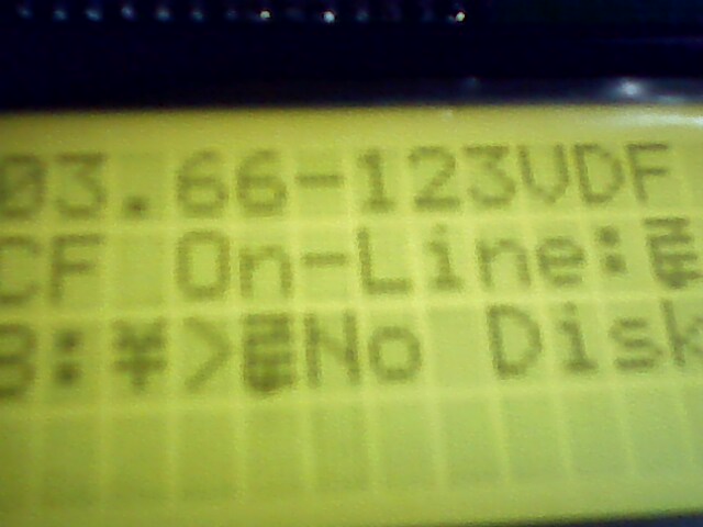
what happened was the pc just printed this:
Ver 03.66-123VDFCF On-Line:
the LED did go high as stated in the program but the vinculum commands seemed that they may not have been recognized.
what do you think is the problem with this? Im running out of clues on why its still not working but i think that the problem is just within the pic microcontroller since the pc had been able to send and receive commands through the max232 or maybe its still the baud rate..
about the hyper terminal's config, yes, it was indeed 9600,8,N,1.
ok,
Lets back up a bit and make sure the PIC is communicating properly.
Connect the PIC to the PC without the MAX232, we will be using inverted mode.
The below code will send to the terminal only when "SOS" is sent to the PIC, from the terminal.
If this does not work then we know the problem is with the PIC... being you can communicate with the VDIP via the PC terminal.
http://www.melabs.com/resources/ser2modes.htmCode:X VAR BYTE X = 0 TXOUT: X = X + 1 SERIN2 PORTC.5,16468,[WAIT("SOS")] SEROUT2 PORTC.4,16468,["MESSAGE RECEIVED!!!",13] SEROUT2 PORTC.4,16468,["THIS IS A TEST",13]'9600 INVERTED SEROUT2 PORTC.4,16468,[DEC X,13] PAUSE 250 GOTO TXOUT
Dave
Always wear safety glasses while programming.
how will i be able to connect the pic16f877a to the rs232 without the use of level coverter? will the pic and the pc be able to understand each other?
and most importantly, wont that be dangerous for my pc?
i will do the interfacing of the pic directly to the pc once i get a reply from you.
knowing that my pc will be safe with the max232., i gave it a try and connected it to the pic. I burned you program and set the config that you've given me to the hyper terminal. the result was, there was no response..i was even having a hard time typing the word SOS because the hyperterminal was slow to respond with every key pressed.
One of the nice things about SERIN2 and SEROUT2 is a 232 is not needed. That is what inverted mode is for. Look in your PBP manual for details for the connection.
You can use a 232 but you will have to change the mode to TRUE.
Hyperterminal..... I do not use it.
I have been using the terminal app that comes with MCS. For this kind of thing it works well.
Dave
Always wear safety glasses while programming.
when i used the max232 i changed the baudrate code to 84...
so you mean i will just have to connect the PORTB.4 and PORTB.5 to the pins 2 and three of the rs232? nothing more as far as hardware are concerned?
I am not sure what you mean by pins 2 and 3 on the 232?
And I was using portC in my code.
The purpose of this exercise is to make sure the PIC is comunicating properly. So look at the PBP manual for the digram to connect the PIC without a 232.
This way we have eliminated a "variable" in the system that could be causing trouble.
One PIC and one PC with a couple resistors.
Dave
Always wear safety glasses while programming.
Im sorry about that..what i meant was PORTC.4 and PORTC.5
and will they be connected to the pins 2 and 3 of the rs232 which i believe is the receive and transmit pins.
what will be the values of the resistors and where will i be putting them?
Last edited by newbie; - 2nd February 2010 at 13:44. Reason: additional question.
Ive did what you told me to do but i had no response from the pc. i even found a code which i think is the simplest serial communication code there is in this page:
http://www.cornerstonerobotics.org/c...out2_hello.pbp
though had to do some changes since the code requires PIC16F88
but still i have no response from the pc...
i also tried to use serout and serin to see if the pic would work with them but still no success..
how can this be when the pic works normally with LCDs, pushbuttons, leds etc...
Hi Newbie,
I am guessing, you do not have the manual. Just put a 1k resistor in series with your PIC ports to the PC. This is to protect the PIC from excessive current, due to the different voltages present in the PC. I suggest you download Realterm (it's free ) and use instead of the Miserable hyperterm in WinDoZE . Send your data inverted without the RS232 converter or if you ARE using it, send your data TRUE.
Example: serout PortC.4,N9600,["Hello World"]
You will have to include modedefs.bas if you use the mode aliases T9600, N9600 . . . . and make sure whatever terminal program you use is connected to the same serial port you are using, that alone may be your problem.
If you do not believe in MAGIC, Consider how currency has value simply by printing it, and is then traded for real assets.
.
Gold is the money of kings, silver is the money of gentlemen, barter is the money of peasants - but debt is the money of slaves
.
There simply is no "Happy Spam" If you do it you will disappear from this forum.
it was already too late when i found the right schematic for interfacing the pic to the pc. my pic was already not working with any program probably because i failed to put a 1k resistor like what Joe said the first time i interfaced it. I will purchase a new pic16f877a right away and get going with my project once again.
finally something good happend...
i can already print the file names inside the flash drive to the LCD
the cause of why i could not print anything earlier was maybe because of the timing of the execution of the command. there where probably times when the vdip was already sending data to the pic but the pic was still busy of doing another thing like printing welcome notes to the lcd (or something like that..) so the data could not the printed to the the lcd.so what i can is, the PAUSE command plays a major role.
as for the printing of the file names, im having trouble arranging the files line by line to the lcd..primarily because they do vary in length and also other weird characters come in between some of the words which i guess are due to the line feed or carriage return..
does anyone have any idea of how i can save a string into a different variable each time a line feed of carriage return is encountered?
or are there any alternative way...id like to see it...
hi, izzit possible to connect vdip2 with hyper terminal using max233 instead of max232
Glad to hear you have something working..Originally Posted by newbie
 i can already print the file names inside the flash drive to the LCD
the cause of why i could not print anything earlier was maybe because of the timing of the execution of the command. there where probably times when the vdip was already sending data to the pic but the pic was still busy of doing another thing like printing welcome notes to the lcd (or something like that..) so the data could not the printed to the the lcd.so what i can is, the PAUSE command plays a major role.
as for the printing of the file names, im having trouble arranging the files line by line to the lcd..primarily because they do vary in length and also other weird characters come in between some of the words which i guess are due to the line feed or carriage return..
does anyone have any idea of how i can save a string into a different variable each time a line feed of carriage return is encountered?
or are there any alternative way...id like to see it...
Joe's idea http://www.picbasic.co.uk/forum/show...7&postcount=73 is probably the way to do this. Just have the string terminate when EOF is returned.
Dave
Always wear safety glasses while programming.
Do you know the difference between the two parts?
Dave
Always wear safety glasses while programming.
line feed is 10 right? if i would have the line feed to an IF statement, how would i get the compiler to understand that I am pertaining to 10 as the line feed and not the number itself? would i need to put a preceding sign like # or $ or should i just put 10 without the "" marks?
are you talking about the array of bytes as the string in here? or is there a way to save the group of characters into one string constant?Just have the string terminate when EOF is returned.
Last edited by newbie; - 9th February 2010 at 16:46. Reason: additional question
hi! here's what has happening to my project so far... ive been interfacing a vdip2, a pic16f877a and a 4x20LCD. i can already print the responses of the vdip to the LCD..but my problem is that some characters appear in between the file names which do not appear when the vdip is connect to the pc. ive searched the ascii tables http://www.ascii-code.com/ to see if these characters have an equivalent hex code so that i can use it for the wait() command in picbasic pro..but i did not find the characters in the table. i first thought that it was a line feed but when i used the code $0A(line feed) for the serial wait() command, it did not work... do you have any idea on these characters are? ive attached some images, you might want to take a look on what these characters look like...
Looks like you about have it!!! Good job!!!
Look at the data sheet for the display and there should be a "Character Font Table". Those characters show up there.
Why the commands are being sent to your display and how to fix it I do not know...
Thinking....
Dave
Always wear safety glasses while programming.
i have a data sheet of the display...some of the characters of the are found in there but some aren't. these reason i have my eyes set on these weird character is because i think they would be the key to sorting the file names since the appear in between them.basing on the pictures above, do you have any idea on how i can sort the file names so that i can print only one file name per line? ive been trying joe's suggestion but so far i have no success.
Hi Newbie,
Sometimes weird characters are due to the clock or baud being off. They can occur if the LCD's power is not bypassed adequately with a capacitor. What I do to check things like this is to make a counter loop which outputs a count from 0 to xxx and also outputs a space after and also outputs the counter variables actual count, and I watch for the character to appear and see what number makes it so.
If you do not believe in MAGIC, Consider how currency has value simply by printing it, and is then traded for real assets.
.
Gold is the money of kings, silver is the money of gentlemen, barter is the money of peasants - but debt is the money of slaves
.
There simply is no "Happy Spam" If you do it you will disappear from this forum.
Something like this
Code:B var word counter var word main: counter = 0 b = 0 lcdout $FE,1 ' Clear LCD for counter = 0 to 255 LCDOUT $fe,$2,b," ",#counter PAUSE 250 b = b + 1 next counter goto main
If you do not believe in MAGIC, Consider how currency has value simply by printing it, and is then traded for real assets.
.
Gold is the money of kings, silver is the money of gentlemen, barter is the money of peasants - but debt is the money of slaves
.
There simply is no "Happy Spam" If you do it you will disappear from this forum.
About a year ago I had the bright idea of using a PIC and a VDIP1 to transfer file to a Burny 2.5 CNC controller. I could never get it working properly and gave up.
The Burny was never happy with the data being sent to it. My simulation software worked fine. I wonder if what newbie is seeing was the problem with the Burny?
Somehow the VDIP is sending "ghost" info??
Dave
Always wear safety glasses while programming.
hi guys thanks for the replies but i think i got it...
the weird characters were carriage returns ($0d).
i used this code..
as you can see i waited for every occurrence of the carriage return and saved the characters found between them into an array of string.Code:CRET VAR BYTE CRET = $0D SERIN2 VinTXD,84,[WAIT(CRET),STR FILE1\12 \CRET,WAIT(CRET), STR FILE2\12 \CRET,WAIT(CRET),STR FILE3\12 \CRET,WAIT(CRET),STR FILE4\12 \CRET]
the weird characters that you can see at the end of some files names in the lcd are i think blank or null arrays since i allocated 12 array places for every file name found but not all of them would be 12 characters long..some are less.
now could you suggest any better way of storing these file names?
because i think if i do it this way, my pic microcontroller would quickly run out of space to save all of the characters from the file names and if the flash drive inserted is very populated then the files names not saved in the array would not be displayed.
If the file names are always the same, you could assign them each a number, and store the names in eprom, or if they have all the same name with a number, even easier, just display the name followed by the number received. Unless I am missing something due to inadequate supply of coffee
If you do not believe in MAGIC, Consider how currency has value simply by printing it, and is then traded for real assets.
.
Gold is the money of kings, silver is the money of gentlemen, barter is the money of peasants - but debt is the money of slaves
.
There simply is no "Happy Spam" If you do it you will disappear from this forum.
You might try what Joe suggested before and pre-populate the arrays with a known value.
Dave
Always wear safety glasses while programming.
here is the rule about the files from the vinculum:If the file names are always the same, you could assign them each a number, and store the names in eprom, or if they have all the same name with a number, even easier, just display the name followed by the number received.
Filenames are made up of an 8 character main part and an optional 3 character extension. The presence of a dot character in the filename indicates the boundary between the main part and the extension. The name may be up to 12 characters long, including the dot character.
can you give me a sample code about this? I'm not that familiar with eproms.
ive been thinking about doing that..but the thing is if the length of the file names is less than 12, i might have trouble retrieving only the arrays that were inserted with the file name characters. if i include the arrays that were not over written by the file name characters and still contains the pre loaded value, the vdip2 would respond "command failed".You might try what Joe suggested before and pre-populate the arrays with a known value.
What if you populate the array with a character that would probably not be used in a file name, (~), and parse the array for that before the array is used again.
Or, have a "working" array. This would be one that stored arrays are parsed into for using.
Stored array with (~) character
Stored array re-written into sandbox array
Sandbox array is sent to VDIP
Start over with next stored array.
Maybe....
Dave
Always wear safety glasses while programming.
 Members who have read this thread : 0
You do not have permission to view the list of names.
 Posting Permissions


Bookmarks