


Automatic Blind System
Hi there,
I'm currently working on project call automatic blind system which is activate depends on outside condition. Before this is tried to build this project MICROCONTROLLER BASED AUTOMATED LIGHT CONTROL SYSTEM which is based on AVR ATMEGA32 but it failed to get what is has supposed to..
Since that i try to switch to PIC and found out using PBP is time saving and cost reduced language since the project submission is just around the corner..I hope PBP master here can fix my code since i wrote this just a day ago with zero knowledge of PBP by just reviewing the manual and project book. Here is the circuit diagram and code. The proteus VSM files will be PM if someone really want to help.
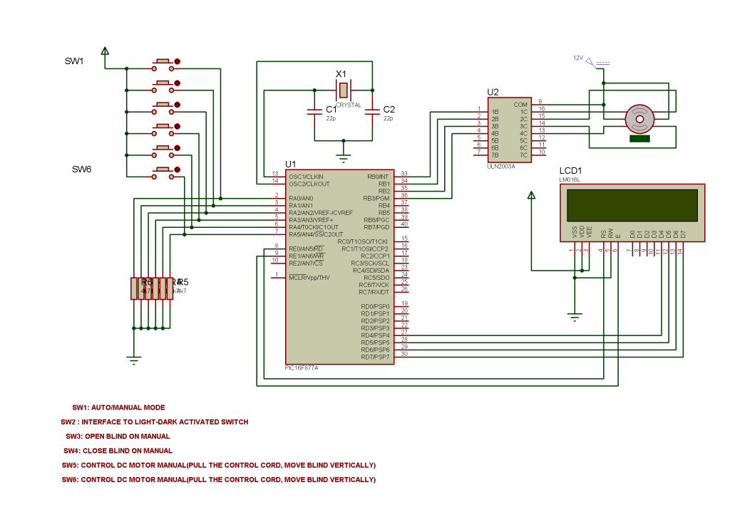
The Circuit
PicBasic Pro code
The operationCode:'**************************************************************** '* Name : 877A_BLIND.BAS * '* Author : PIJO RAHMAN * '* Notice : Copyright (c) 2008 [select VIEW...EDITOR OPTIONS] * '* : All Rights Reserved * '* Date : 11/4/2008 * '* Version : 1.0 * '* Notes : Using PIC16F877A to control Vertical Blind Auto * '* and Manual with light sensor * '**************************************************************** DEFINE OSC 4 '**************************************************************** CMCON = 7 ADCON1 = 7 TRISB = 0 ' Set PortB as output TRISA = 1 ' Or TRISA = 255, set PortA as input '*************************************************************** Define LCD_DREG PORTD 'Based on Rentron 877A LCD Connection Define LCD_DBIT 4 Define LCD_RSREG PORTE Define LCD_RSBIT 0 Define LCD_EREG PORTE Define LCD_EBIT 1 B1 VAR BYTE 'Declared Byte For LCD Splash Screen B0 VAR BYTE B2 VAR BYTE B3 VAR BYTE B4 VAR BYTE B5 VAR BYTE '**************************************************************** clear 'clear all variables LCDOUT $FE,1 'clear lcd PAUSE 500 'pause for lcd init Low PORTE.2 'LCD R/W line low (W) '************************************************************** '*****************slide text for splash screen************************** LOOP: LCDOut $fe,2 For B2= 0 TO 15 LookUp B0, [" AUTOMATIC BLIND SYSTEM #"], B1 IF B1 = "#" Then GoTo reset LCDOut B1 B0 = B0 + 1 Next B2 pause 125 'character wait time B0 = B0 - 15 GoTo loop RESET: LCDOUT $FE,1 '************************************************************************ CREDIT: 'Display Presenter Credit LCDOUT $FE,$80 LCDOUT "PRESENTER NAME" 'presenter credit 'LCDOUT $FE,$C0 'LCDOUT " GROUP " 'presenter credit PAUSE 1500 LCDOUT $FE,1 speed var word speed = 100 ;i var byte Main: ' Main Prgm, Check Button for Auto/Manual Op IF PORTA.0=1 THEN Manual If PORTA.1=1 Then ForwardM If PORTA.1=0 Then ReversesM Goto Main End Manual: 'FOR MANUAL OPERATION START WITH RA0=1 THEN CONTROL RA2 AND RA3 Pause 500 'Do it about 2 times a second LCDOUT $FE,1 'Clear LCD LCDOUT $FE,$80,"MANUAL" 'Display "Manual" 1st Line on LCD LCDOUT $FE,$C0,"USER INPUT" 'Display "USER INPUT" 2nd Line on LCD IF PORTA.2=1 THEN FORWARDM 'Manually Opening Blind IF PORTA.3=1 Then ReversesM 'Manually Closing Blind Goto Main ForwardM: LCDOUT $FE,1 LCDOUT $FE,$80,"OPENING BLIND" LCDOUT $FE,$C0,"DAYLIGHT" ;FOR i = 1 TO 5 ' one revolution 'Actually Use this Function for Revolution Step But No LUCK! :( GOto Forward ' rotate clockwise ;NEXT i GOTO Main ReversesM: LCDOUT $FE,1 'Clear LCD LCDOUT $FE,$80,"CLOSING BLIND" LCDOUT $FE,$C0,"SUNSET/DARK" ;FOR i = 1 TO 5 ' one revolution Goto Reverses ' rotate counter-clockwise ;NEXT i GOTO Main Forward: 'Stepper Motor Clockwise Sequence portb = %1100 pause speed portb = %0110 pause speed portb = %0011 pause speed portb = %1001 pause speed Goto Main Reverses: 'Stepper Motor AntiClockwise Sequence portb = %1001 pause speed portb = %0011 pause speed portb = %0110 pause speed portb = %1100 pause speed Goto Main END
This project is simple as it shows. The circuit is consist of manual and automatic function. SW1 connected at RA0 is to use to switch between auto/manual mode. In auto mode, all the manual control switch which is SW3 and SW4 is not activated but only receive the signal from SW2 [which is will be interface to light-dark activated switch, so no ADC will be required]. If SW2 high, motor is rotate clockwise and the blind is open, but if SW2 low, motor is rotate anticlockwise and the blind is close.It need 10 stepper motor revolution [according to my blind] to open and close the blind slat, which is i dunno how to program it.... so even the switch is still in high, the stepper only rotate 10 times and stop and wait till the other state. The stepper motor that I use is common 1.8 degree per step.
The operation repeated until someone invoke the manual switch.
Other switch which is SW5-SW6 is to use to control blind vertical position by using simple DC motor interface to L293D which is will be added later on. The LCD 16x2 is only to display operations, since PIC16F877A still have the unused port.
p/s: If someone interested in this project or feel free to help, just pm me to get the proteus VSM files. Since the dateline is only a week, I hope someone can help me urgently..Thanks in advance!


Bookmarks