GPS clock timing !


Closed Thread
Results 1 to 12 of 12
  1. #1
    Join Date
    Jul 2006
    Posts
    22

    Default GPS clock timing !

    Dear Forum:

    I'd like to build a small Clock with GPS time-sync, look, I'm using the Darrel instant interrups to drive the Timer 1 clock, it works great ! (Thanks Darrel !), but when I tried to read the GPS data (over Pin RB1) there is a lot of missed/corrupted bytes in my buffer, something like this:

    the first lcd line is the RMC message data (corrupted in this case) and the second line display the RTC registers, (plese note tha my LCD was broken so the lower line is wrong )

    this is the code
    Code:
    '''''''''''''' INCLUDES ''''''''''''''''''''''''''''''''''''	
    	DEFINE OSC 4 
    	INCLUDE "DT_INTS-18.bas"
    	INCLUDE "ReEnterPBP-18.bas"
    	INCLUDE "Elapsed_INT-18.bas"  
    	INCLUDE "LCDPICDEM2.BAS"		' it runs on PIDEM2 PLUS Board
    
    ''''''''''''' VARIABLES ''''''''''''''''''''''''''''''''''''	
    		j    var byte
    		rmc  var byte[100]	' this gets RMC data
    		led1 var  portb.2
    		b0   var byte
    		adcon1 =$07
    		trisa.2 = 0
    		trisa.4 = 1
    		trisb.1 = 1
    		trisb.2 = 0
    		trisb.0 = 1
    		trisc.2 = 0
    	    porta.2 = 0
    		gps var portb.1
    	 	spk    var portc.2
    
    ''''''''''''' CODE ''''''''''''''''''''''''''''''''''''	
    	
    init:	
    	ASM
    	INT_LIST  macro    ; IntSource,        Label,  Type, ResetFlag?
    	        INT_Handler   TMR1_INT,  _ClockCount,   PBP,  yes
    	        endm
    	INT_CREATE                 
    	ENDASM
    	T0CON = %10011010
    	@    INT_ENABLE  TMR1_INT      
    	GOSUB ResetTime
    	GOSUB StartTimer           
    	hours = 11 : minutes = 30: seconds = 0
        
    Start:
    	LCDOUT $FE,1                    ' Initialize LCD
    	PAUSE  200	
    	lcdout $fe,2,"Starting ..." : pause 500
    
    Main:
     
    	serin2 gps,188,1000,no_gps,[wait("MC"),str rmc\15\10]	'15 bytes only for testing () wait for RMC message
     
    	lcdout $fe,$c0,"Time : ",dec2 hours,":",dec2 minutes,":",dec2 seconds
     
    	lcdout $fe,2,"$",str rmc\15 :pause 500						' these are the bytes as captured !
    	goto main
    
    no_gps:
    	lcdout $fe,2,"Np Gps stream ": pause 500
    	goto  main
    '''''''''''''''''''''''''''''''''''''''''''''''''''''''''''''''''''''''''''
    my first idea to fix it,was stop the timer just before get the gps data stream, like this:

    Code:
    	gosub stoptimer
    	serin2 gps,188,1000,no_gps,[wait("MC"),str rmc\15\10]	'15 bytes only for testing () wait for RMC message
    	gosub starttimer
    using above lines my LCD looks like this:

    looks good !!!


    but here, I have a problem with the time !, this make delay on the RTC, If I just was updated my clock register each ten minutes or so, that work out very well, but I want to keep my RTC all the time, (for logging timed-stamp GPS locations by example).

    I knew this is a time issue (software generated timing "serin2"), another plan is to use the internal UART build in my pic (i'm using a18f452), but my GPS only outputs TTL levels this create interfacing problems, how can I get working this project?

    Thanks !!!
    Last edited by bethr; - 1st July 2008 at 18:44.

  2. #2
    skimask's Avatar
    skimask Guest


    Did you find this post helpful? Yes | No

    Default

    Quote Originally Posted by bethr View Post
    I'd like to build a small Clock with GPS time-sync, look, I'm using the Darrel instant interrups to drive the Timer 1 clock, it works great ! (Thanks Darrel !), but when I tried to read the GPS data (over Pin RB1) there is a lot of missed/corrupted bytes in my buffer, something like this:
    Probably the interrupts interrupting the SERIN statements. Disable the interrupts before going into SERIN, reenable after coming back.

    I knew this is a time issue (software generated timing "serin2"), another plan is to use the internal UART build in my pic (i'm using a18f452), but my GPS only outputs TTL levels this create interfacing problems, how can I get working this project?
    Normal, Inverted RS232, the PICs capabilities, all discussed fairly well in the PBP manual.

  3. #3
    Join Date
    Jul 2003
    Location
    Colorado Springs
    Posts
    4,959


    Did you find this post helpful? Yes | No

    Default

    Since you're using a GPS, you already have a clock that's more accurate than anything you could possibly add to a PIC.

    Just read the GPS time to use as a time stamp in the logs.

    OR, a single transistor with 2 resistors can invert the serial data to the USART, if you still want the internal clock.
    <br>
    DT

  4. #4
    Join Date
    Jul 2003
    Location
    Colorado Springs
    Posts
    4,959


    Did you find this post helpful? Yes | No

    Default

    OOPs.

    I just looked up the 188 from your SERIN2 statement.

    That's 4800 baud TRUE levels.
    You can hook it up to the USART's RX pin. No transistor needed.

    hth,
    DT

  5. #5
    Join Date
    Jul 2006
    Posts
    22


    Did you find this post helpful? Yes | No

    Default

    Thanks by answer Skimask, Darrel !
    you both Are right, there is no interfacing conflicts, but unfortunately I always get the ' no gps ' string on the LCD (with or without running the RTC), I mean, I have made changes for using Hserin instead serin2,
    Code:
    '''''''''''''' INCLUDES ''''''''''''''''''''''''''''''''''''	
    	DEFINE OSC 4 
    	INCLUDE "DT_INTS-18.bas"
    	INCLUDE "ReEnterPBP-18.bas"
    	INCLUDE "Elapsed_INT-18.bas"  
    	INCLUDE "LCDPICDEM2.BAS"		' it runs on PIDEM2 PLUS Board
    	
    	DEFINE HSER_TXSTA 20h
    	DEFINE HSER_RCSTA 90h
    	DEFINE HSER_BAUD 4800
    
    ''''''''''''' VARIABLES ''''''''''''''''''''''''''''''''''''	
    		j    var byte
    		rmc  var byte[100]	' this gets RMC data
    		led1 var  portb.2
    		b0   var byte
    		adcon1 =$07
    		trisa.2 = 0
    		trisa.4 = 1
    		trisb.1 = 1
    		trisb.2 = 0
    		trisb.0 = 1
    		trisc.2 = 0
    		trisc.7 = 1
    	    porta.2 = 0
    		gps var portb.1
    	 	spk    var portc.2
    
    ''''''''''''' CODE ''''''''''''''''''''''''''''''''''''	
    	
    init:	
    	ASM
    	INT_LIST  macro    ; IntSource,        Label,  Type, ResetFlag?
    	        INT_Handler   TMR1_INT,  _ClockCount,   PBP,  yes
    	        endm
    	INT_CREATE                 
    	ENDASM 
    
    	@    INT_ENABLE  TMR1_INT      
    	GOSUB ResetTime
    	GOSUB StartTimer           
    	hours = 11 : minutes = 30: seconds = 0
        
    Start:
    	LCDOUT $FE,1                    ' Initialize LCD
    	PAUSE  200	
    	lcdout $fe,2,"Starting ..." : pause 500
    
    Main:  
    	Hserin 1500,no_gps,[wait("MC"),str rmc\15\10]	'15 bytes only for testing () wait for RMC message
      
    
    	lcdout $fe,$c0,"Time : ",dec2 hours,":",dec2 minutes,":",dec2 seconds
     
    	lcdout $fe,2,"$",str rmc\15 :pause 500						' these are the bytes as captured !
    	goto main
    
    no_gps:
     
    	lcdout $fe,1,"No Gps stream "
    	lcdout $fe,$c0,"Time : ",dec2 hours,":",dec2 minutes,":",dec2 seconds
    	goto  main
    '''''''''''''''''''''''''''''''''''''''''''''''''''''''''''''''''''''''''''


    currently for debug I'm using an GPS software simulator:


    and I'm sure that it works, this is a debug rs232 window (hyperterm)

    that was taken on Sub-DB9 connector of the picdem2 board

    there is something missing in the set-up hardware UART ???

    Thanks again !

  6. #6
    Join Date
    Jul 2003
    Location
    Colorado Springs
    Posts
    4,959


    Did you find this post helpful? Yes | No

    Default

    Try it like this...
    Code:
    	DEFINE HSER_TXSTA 24h ' BRGH=1
    	DEFINE HSER_RCSTA 90h
    	DEFINE HSER_BAUD 4800
            DEFINE HSER_CLROERR 1 'Hser clear overflow automatically
    DT

  7. #7
    Join Date
    Jul 2006
    Posts
    22


    Did you find this post helpful? Yes | No

    Smile

    It's alive !!

    it works Darrel, I'm wondered why this bit must be set in hi speed if my bps is low ! (4800 bps)

    Code:
    
    bit 2 BRGH: High Baud Rate Select bit
    Asynchronous mode:
    1 = High speed
    0 = Low speed
    and now it looks run pretty ! (with RTC running ), look this:


    Now, I'll keep it running for a while, I hope the RTC doesn't have long-delays. any-way as you said, always there is way to update ths RTC register with GPS ones !!
    BTW currently I'm not using UART interrupts, but . . .
    . . . what if . . .

    I enable it ?, this give more reliable data incoming form the GPS line ? or it can be dangerous for the RTC health ?

    Last edited by bethr; - 2nd July 2008 at 00:47.

  8. #8
    Join Date
    Jul 2003
    Location
    Colorado Springs
    Posts
    4,959


    Did you find this post helpful? Yes | No

    Default

    Quote Originally Posted by bethr View Post
    It's alive !!
    WooHoo!

    I'm wondered why this bit must be set in hi speed if my bps is low ! (4800 bps)
    With a 4mhz OSC, I wouldn't consider 4800 "low".

    In the datasheet there's a couple tables that show the baud rates vs. OSC freq with BRGH either 1 or 0. With BRGH=0 @ 4mhz, the highest baudrate in the table is 2400. With BRGH=1 it's 19200.

    It may still work with BRGH=0, but it's close to the edge, so why not just make it BRGH=1.

    I think the HSER_CLROERR 1 may have had the biggest effect.
    The GPS will just spit out the data at regular intervals. It doesn't wait for the PIC to be ready. And at 4800 baud it can send a byte every 2ms. So when the program sits in a 500 ms pause, it may receive a couple hundred bytes before the program gets around to looking at the data. There's only a 2 byte buffer in the USART so it causes an Overflow that must be cleared before it will start receiving data again.

    BTW currently I'm not using UART interrupts, but . . .
    . . . what if . . .

    I enable it ?, this give more reliable data incoming form the GPS line ? or it can be dangerous for the RTC health ?
    HSERIN is not compatible with USART interrupts.
    You would need to parse the incomming data 1 byte at a time with your own handlers.

    It's much easier to use HSERIN.

    hth,
    DT

  9. #9
    Join Date
    Jul 2006
    Posts
    22


    Did you find this post helpful? Yes | No

    Talking

    Yes you're Right, I think that on this way the gps clock work well, there is no problem with it, I have it running & all looks nice !

    The program doesn't anything important (just led blinking), and when BTN rb0 is pushed, it gets info from GPS module and update my RTC registers just as i wanted !

    Code:
     
    'BETHR
    '''''''''''''' INCLUDES ''''''''''''''''''''''''''''''''''''	
    	DEFINE OSC 4
    	INCLUDE "DT_INTS-18.bas"
    	INCLUDE "ReEnterPBP-18.bas"
    	INCLUDE "Elapsed_INT-18.bas"  
    	INCLUDE "LCDPICDEM2.BAS"		' it runs on PIDEM2 PLUS Board
    	DEFINE HSER_TXSTA 24h 			' BRGH=1
    	DEFINE HSER_RCSTA 90h
            DEFINE HSER_CLROERR 1 			' Hser clear overflow automatically
    	DEFINE HSER_SPBRG 51
    
    ''''''''''''' VARS ''''''''''''''''''''''''''''''''''''	
    		led   var Portb.2
    		timeh var byte
    		timem var byte
    		times var byte
    		day	  var byte
    		mon   var byte
    		yr    var byte
    		stat  var byte
    		gps   var Portb.1 
    		TRISB.2 = 0
    		TRISB.0 = 1 
        	         Adcon1 = $07
    
    '''''''''''''''''''''''''''''''''''''''''''''''''''''''''''''''''''''''''''  
    	
    init:	
    	ASM
    	INT_LIST  macro    ; IntSource,        Label,  Type, ResetFlag?
    	        INT_Handler   TMR1_INT,  _ClockCount,   PBP,  yes
    	        endm
    	INT_CREATE                 
    	ENDASM 
    
    	@    INT_ENABLE  TMR1_INT      
    	Gosub ResetTime
    	Gosub StartTimer           
    	hours = 12 'after reset we always star @12:00:00
        
    Start:
    	lcdout $fe,1,"GPS Clock "
        Pause 500
    
    ''''''''''''''''''''''''''''''''''''''''''''''''''''''''''''''''''''''''''' 
    Main: 
    	While 1
    'do something [  something more useful than this :-)  ]
    		While (portb.0=1)
    			Toggle led
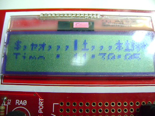
    			Lcdout $fe,2,"Date : ",dec2 day,47,dec2 mon,47,dec2 yr
    			Lcdout $fe,$c0,"Time : ",dec2 hours,":",dec2 minutes,":",dec2 seconds
    		 	Pause 200
    		Wend
    ' if i press rb0 btn update my RTC
    		Gosub Update_rtc
    
    	Wend
     
    ''''''''''''''''''''''''''''''''''''''''''''''''''''''''''''''''''''''''''' 
     
    ''' SUBS ''''
    Update_rtc:
    'look 4 stream
    	lcdout $fe,1,"Updating..."
    	Hserin 500,no_gps,[WAIT("MC,"),dec2 TIMEH,dec2 TIMEM,dec2 TIMES,SKIP 5,_
    	STAT,skip 30,dec2 day,dec2 mon,dec2 yr]	
    'check 4 Valid GPS if so, then update my RTC
    	if stat = "A" then
    		hours=timeh - 5 : minutes = timem: seconds = times
    'no gps so don't update 
    	else
    		lcdout $fe,1,"Bad Fix" : pause 500
      	endif
    	return
    'np gps or bad sintax
    no_gps:   
    	lcdout $fe,1,"No Gps stream" : pause 500
    	return
    ''' END SUBS '''' 
    I've had to replace my broken LCD also !!


    BIG TNX !

  10. #10
    Join Date
    Jan 2007
    Location
    Houston, TX
    Posts
    96


    Did you find this post helpful? Yes | No

    Default GPS info

    Hi there Bethr,
    I am looking at purchasing a garmin LVS gps for a robot project and I was just wondering what kind of gps you are using? Cost? etc....
    Padawan-78

  11. #11
    skimask's Avatar
    skimask Guest


    Did you find this post helpful? Yes | No

    Default

    Quote Originally Posted by earltyso View Post
    Hi there Bethr,
    I am looking at purchasing a garmin LVS gps for a robot project and I was just wondering what kind of gps you are using? Cost? etc....
    If it has an NMEA serial output line, then you can get usable data out of it.
    www.sparkfun.com has a few GPS modules already mounted, ready to use.

  12. #12
    Join Date
    Jul 2006
    Posts
    22


    Did you find this post helpful? Yes | No

    Default

    Quote Originally Posted by earltyso View Post
    Hi there Bethr,
    I am looking at purchasing a garmin LVS gps for a robot project and I was just wondering what kind of gps you are using? Cost? etc....
    currently I have two modules

    this:


    http://www.trimble.com/embeddedsyste...?dtID=overview

    and this one , a low profile asian embedded device:


    both were removed from used equipment, but I know that the trimble module have a cost near to 50 usd (versus qty)
    and the other one near to 30 usd

    both devices has NMEA ascii output @t vdd levels, trimble vdd=3v3 and asian device vdd=5v

    Cheers !!

Similar Threads

  1. GPS $GPRMC to PIC16F684. Need help with SERIN2
    By xnihilo in forum mel PIC BASIC Pro
    Replies: 5
    Last Post: - 27th November 2009, 09:47
  2. Shiftout/in
    By BobEdge in forum mel PIC BASIC Pro
    Replies: 5
    Last Post: - 23rd August 2007, 11:48
  3. Help with sound command in 2 programs
    By hyperboarder in forum mel PIC BASIC Pro
    Replies: 4
    Last Post: - 5th July 2007, 20:36
  4. Replies: 2
    Last Post: - 28th April 2006, 12:10
  5. GPS Receiver
    By lester in forum Adverts
    Replies: 2
    Last Post: - 22nd February 2006, 12:47

Members who have read this thread : 1

You do not have permission to view the list of names.

Posting Permissions

  • You may not post new threads
  • You may not post replies
  • You may not post attachments
  • You may not edit your posts