IR problems


Closed Thread
Results 1 to 11 of 11

Thread: IR problems

  1. #1
    Join Date
    Apr 2007
    Location
    Southern Ontario
    Posts
    50

    Default IR problems

    I would like a clean crisp voltage drop to give my pic a definite 0 or 5 volt difference. the problem is that if I am using an IR transistor (which I need to use) I can dim the led (with a comparitor circuit) by slowly covering the ir reciever (collector). My question is this.. can I create a circuit that will not dim a led ( meaning not a definat on or off) when I need a digital high or low signal... and I have already tried the 741 op amp comparitor. It dims the led as much as the straight transistor does. Could it be the resistors involved?
    all I want is a way of telling the pic that I have a high (5 v)or low (<1.5v)signal. I think it is called hysteria,, Would a shmit trigger work?
    Thank You For The Great Work
    Snap
    Beer is proof that God loves us and wants us to be happy.

  2. #2
    Join Date
    Feb 2003
    Posts
    432


    Did you find this post helpful? Yes | No

    Default

    Quote Originally Posted by Snap View Post
    I would like a clean crisp voltage drop to give my pic a definite 0 or 5 volt difference. the problem is that if I am using an IR transistor (which I need to use) I can dim the led (with a comparitor circuit) by slowly covering the ir reciever (collector). My question is this.. can I create a circuit that will not dim a led ( meaning not a definat on or off) when I need a digital high or low signal... and I have already tried the 741 op amp comparitor. It dims the led as much as the straight transistor does. Could it be the resistors involved?
    all I want is a way of telling the pic that I have a high (5 v)or low (<1.5v)signal. I think it is called hysteria,, Would a shmit trigger work?
    Thank You For The Great Work
    Snap
    It would be helpful if you could describe the application more clearly.

    What are you trying to make ?

    If it is an IR receiver then using a dedicated IR Receiver module is by ar the most reliable.

    If it is some form of beam break device then again I would use a dedicated IR receiver module but you would need to modulate the IR source with a 38kHz carrier.
    Keith

    www.diyha.co.uk
    www.kat5.tv

  3. #3
    Join Date
    Jul 2003
    Posts
    2,405


    Did you find this post helpful? Yes | No

    Default

    Most PICs have a few Schmitt Trigger inputs. Some have comparators. So
    you can probably make it work without any additional hardware. Just use a
    pin with a Schmitt Trigger input buffer, or the built-in comparator.

    In the PIC data sheet, the port block diagrams show which pins have Schmitt
    Trigger input buffers.

    The Electrcal Specifications section of the data sheet shows what the min
    and max input levels are for high/low signals on different input types.

    As Keith mentioned, the simplest way would be to just use an IR module with
    a built-in band-pass filter of 38 or 40kHz, and modulate your IR LED at the
    band-pass frequency of the module.

    These respond pretty fast with a low-going signal when the IR LED is on, and
    high-going signal when it's off. They work pretty much the same on TTL or
    Schmitt Trigger inputs.

    They are also less sensitive to ambient light than most IR photo transistors,
    and have built-in filters to block light outside the IR wavelength.

    So you save a ton of board space, use fewer parts, and save yourself a little
    hysteria..;}
    Regards,

    -Bruce
    tech at rentron.com
    http://www.rentron.com

  4. #4
    Join Date
    Apr 2007
    Location
    Southern Ontario
    Posts
    50


    Did you find this post helpful? Yes | No

    Default Thank you for the help

    I am making a simple beam breaker. I have an infra red emitter and detector (photo transistor) but need to get the signal into the pic (16f84a). I was just wondering how to start with the cleanest signal I could (0 or 5 volts not 1.2 or 2.3 volts) I perfer not going with the pre-made units because I am trying to understand how it works. All of the circuits I find involve op amps and technically the out put should but just that (0 or 5volts) or pretty darn close. I set it up and if I break the beam very slowly you can see the led dimly start to light before it comes fully on. I played around with lots of resistor combinations but it does not seem to make a difference. I want a relay type of instantanious change.
    Thanks again for your help and sorry for the Hysteria I am a big Def Lepard fan and I can't find the spell checker on this thing.
    Beer is proof that God loves us and wants us to be happy.

  5. #5
    Join Date
    Jul 2003
    Posts
    2,405


    Did you find this post helpful? Yes | No

    Default

    Here's one example using a comparator. http://home.cogeco.ca/~rpaisley4/ATDetIR.html
    Regards,

    -Bruce
    tech at rentron.com
    http://www.rentron.com

  6. #6
    Join Date
    Nov 2003
    Location
    Wellton, U.S.A.
    Posts
    5,924


    Did you find this post helpful? Yes | No

    Default

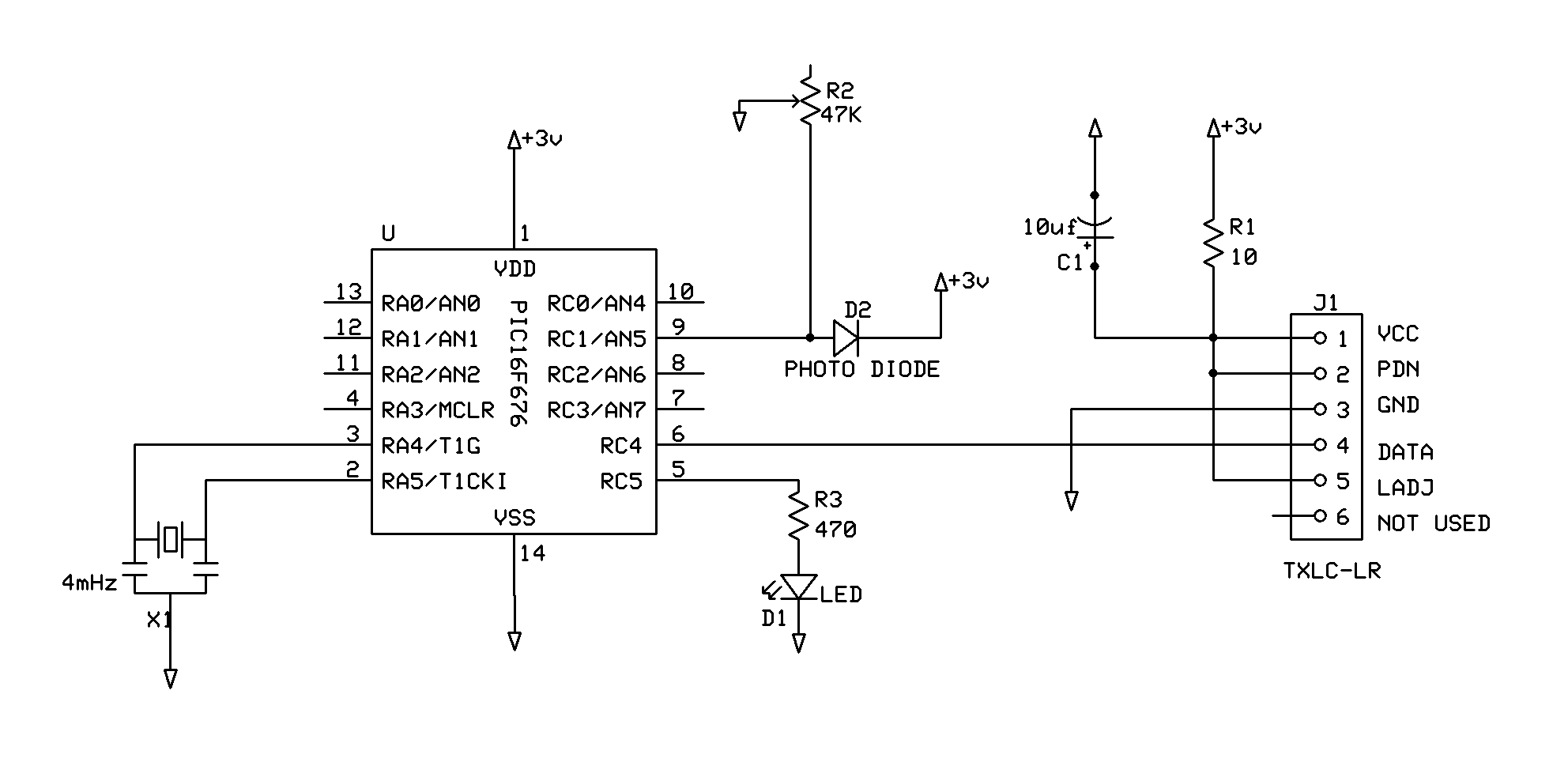
    Here is one I am using for a "Laser Fence". It will also work for IR.

    And the simple code to go with it.
    Code:
    DEFINE OSC 4
    
    Asm
        ERRORLEVEL -306
    Endasm
    
    include "modedefs.bas"
    
    ANSEL=%00000000
    CMCON=7
    
    PAUSE 2000
    
    TRAIN	VAR BYTE
    
    TRAIN=$55
    CNT	VAR BYTE
    LP	VAR BYTE
    
    START:
    COUNT PORTC.1,100,LP
    IF LP <> 1 THEN CHECK
    HIGH PORTC.5
    PAUSE 50
    LOW PORTC.5
    PAUSE 50
    GOTO START
    
    CHECK:
    COUNT PORTC.1,100,LP
    IF LP <> 1 THEN BREACH
    GOTO START
    
    BREACH:
    FOR CNT = 1 TO 5
    SEROUT PORTC.4,T2400,[TRAIN,TRAIN,TRAIN,TRAIN,TRAIN,9,3]
    HIGH PORTC.5
    PAUSE 100
    NEXT
    GOTO START
    
    END
    R2 will adjust the sensitivity of the Photo Diode. Ambient light does need to be shielded. Have used the same with IR but R2 was a fixed 10meg. (Total darkness for a parts counter on a conveyor)

    Using 3 volts because of the radio transmitter.
    Attached Images Attached Images  
    Dave
    Always wear safety glasses while programming.

  7. #7
    Join Date
    Nov 2003
    Location
    Wellton, U.S.A.
    Posts
    5,924


    Did you find this post helpful? Yes | No

    Default

    Looks like I need a lesson on image tags!
    <img src="http://www.picbasic.co.uk/forum/attachment.php?attachmentid=1904&stc=1&d=118608738 4">

    Got it!!
    Attached Images Attached Images  
    Last edited by mackrackit; - 2nd August 2007 at 21:47. Reason: Image problem
    Dave
    Always wear safety glasses while programming.

  8. #8
    Join Date
    Apr 2007
    Location
    Southern Ontario
    Posts
    50


    Did you find this post helpful? Yes | No

    Default

    I am happy there are more people out there building things for their .....ahem..childrens amusment. Mine is a slot car track for my son. Bruce small internet I used the exact same schematic you sent me for the lay out and it is the one that is giving me the problems but Im sure I am being too sticky about the details and tonight I will try it out with the pic with the fence circuit and see how it works (in sure it will be great).
    Thanks again for the help I will post if it works or not.
    Snap
    Beer is proof that God loves us and wants us to be happy.

  9. #9
    Join Date
    Apr 2006
    Location
    New Hampshire USA
    Posts
    298


    Did you find this post helpful? Yes | No

    Default image tags

    Quote Originally Posted by mackrackit View Post
    Looks like I need a lesson on image tags!
    Found this:
    [html]<img src="http://www.picbasic.co.uk/forum/attachment.php?attachmentid=367">[/html]By: Darrel
    Here:
    http://www.picbasic.co.uk/forum/show...98&postcount=2

  10. #10
    Join Date
    Nov 2003
    Location
    Wellton, U.S.A.
    Posts
    5,924


    Did you find this post helpful? Yes | No

    Default

    Quote Originally Posted by Pic_User View Post
    Found this:
    [html]<img src="http://www.picbasic.co.uk/forum/attachment.php?attachmentid=367">[/html]By: Darrel
    Here:
    http://www.picbasic.co.uk/forum/show...98&postcount=2
    Thank you Pic_User! Learn something every day.
    Dave
    Always wear safety glasses while programming.

  11. #11
    Join Date
    Apr 2007
    Location
    Southern Ontario
    Posts
    50


    Did you find this post helpful? Yes | No

    Default It works ???

    Ok, I got my ir detect to work on a pic 16f84a the secret is to ignore all of the internet info out there that suggest op amps comparators. The pic is smart enough to read a slightly variable input (you might have to pull up of down the port). and job is done. After all was working It still bugged me that I could not get the 741 op-amp working so I spent the night playing with diffent combinations of resistors and leds untill I thought I figured this little sucker out of course I will be wrong ...but I can tell you that the fence circut works.
    Thank again for the speedy help
    Snap
    Beer is proof that God loves us and wants us to be happy.

Similar Threads

  1. Replies: 17
    Last Post: - 12th April 2014, 02:17
  2. Having problems with IR Remote circuit.........
    By sanddune008 in forum General
    Replies: 1
    Last Post: - 19th November 2008, 12:02
  3. Plz help in completing RC-5 IR remote lamp dimmer project
    By vu2iia in forum mel PIC BASIC Pro
    Replies: 3
    Last Post: - 3rd April 2008, 08:44
  4. PIC10F200 Automated IR Light Switch
    By Bruce in forum Code Examples
    Replies: 7
    Last Post: - 3rd May 2007, 11:40
  5. how to get pic to pic communication
    By kinsiro in forum mel PIC BASIC Pro
    Replies: 5
    Last Post: - 30th August 2005, 17:12

Members who have read this thread : 1

You do not have permission to view the list of names.

Posting Permissions

  • You may not post new threads
  • You may not post replies
  • You may not post attachments
  • You may not edit your posts