


How often is safe to update the HPWM duty cycle when running a 12f683 at 4mhz?
I see that doing it constantly confuses the uC, so whats the safe "wait period" ?
Thanks!

How often is safe to update the HPWM duty cycle when running a 12f683 at 4mhz?
I see that doing it constantly confuses the uC, so whats the safe "wait period" ?
Thanks!

What do you mean by 'safe' and 'confuses the uC'?Originally Posted by peu

Hi Skimask,
I mean if I update the HPWM inside the main loop of a program, is it safe to update it every time the loop loops?
From my experimentation (Im controlling LED brightness using this hpwm) if I do this the LED flickers.
On the contrary, if I create a 3 lines new program with just one HPWM line and a loop:gotoloop, the LED does not flicker at all, its stable as it should be.
thanks
PIC12F683 datasheet, Section 11.3.3
here is the gist of the code im running:
@ device pic12f683,INTRC_OSC_NOCLKOUT , wdt_on, mclr_off, protect_off
DEFINE OSC 4
DEFINE ADC_BITS 10
DEFINE ADC_SAMPLEUS 50
ANSEL = %00000010 ' GPIO.1 A/D in, rest digital
TRISIO = %00010010 ' GPIO.1 lectura AD,
cmcon0 = %00000100 ' AD via gpio1 and internal reference
vrcon = %10001010 ' set vref=2.25v
.
.
.
loop:
oldpote=pote
ADCIN 1, pote ' (0-65535)
if oldpote <> pote then
hpwm 1,inverduty,frecu 'these values are calculated in other section
endif
goto loop
maybe the problem is that im using ADC and HPWM simultaneously?
I don't undertand what you implied by reading that section of the DS.
Thanks!
Last edited by peu; - 5th May 2007 at 23:04.

That's just his little way of saying "I don't Know, go read the datasheet or something."<hr>
When an HPWM command executes, it treats it like it's the First time, and sets up every register needed to run PWM with the CCP module.
Changing CCP and TMR2 registers while the CCP is running PWM will cause "false pulses", Cycle Resets or elongation.
It would be nice if there was an HPWM_UPDATE command that only changed the dutycycle, without messing with the other registers. But there isn't.
If you need a totally "Glitch Free" PWM signal, then you'll have to modify the dutycycle manually. You can still use HPWM to set everything up. And then just modify the dutycycle later, after the PWM is running.
If you haven't already, you should get a copy of mister_e's PicMultiCalc.exe
It'll help figure out what values to use for the dutycycles.
http://www.mister-e.org/pages/utilitiespag.html
HTH,
DT
Thanks for the reply Darrel, now that explains many things
After many tries I managed to make the mister-e app work, it gave me an unregistered class error, but after a little googling I solved, it.
baaaack to the protoboard!
well, now I have a new difficulty, trying to understand the calculator
Running OSC at 4mhz and PWM at 1khz I get:
And I found a post where Mister_e explains how to use it:
If I understand correctly what you posted, I can start the HPWM before the main loop by using for example: HPMW 0,0,1000 and then within the loop adjust just the dutycycle.Code:' ' 38KHz PWM @ 4MHZ using a PIC16F877 ' ---------------------------------- @ __CONFIG _XT_OSC & _LVP_OFF ' ' TRISC = 0 Duty var byte ' ' PWM SETUP ' ========= ' PicMultiCalc says.. ' Duty value for 50%=52 ' PR2 = 25 ' PRESCALLER 1:1 ' ' duty = 52 ' duty value for 50% duty cycle PR2 = 25 ' T2CON = %00000100 ' timer2 on, prescale 1:1 CCPR1L = duty>>2 ' MSB of duty cycle value CCP1CON=%00001100 | (dUTY<<5) ' set PWM mode and store the ' 2 LSB of duty SpinInRound: goto spininround
Now what I dont understand is how I change the duty cycle, by using the calc I get 1000 values, but the duty variable is defined as BYTE
I could use some help/hint
Thanks!
well it seems Im having a conversation with myself, instead of busting the few neurones I have left, I used the second option (prescaler 1:16) and I made it work, but the glitches are still there.
I initialized the PMW before the main loop using: HPWM 0,0,1000
and the registers as:
T2CON = %00000110 ' timer2 on, prescale 1:16
PR2 = 62 'per pic calculator
and every time I wanted to adjust the duty cycle I entered the value in the duty variable and called this subroutine:
CCPR1L = duty>>2
CCP1CON=%00001100 | (duty<<5)
As I said...the glitches remain... if I stop reading the ADC they dissapear and the PWM is steady
HELP !

first you'll have to match the calc values to suit your need. With your current code example (which seems to be one of mine, the calc will give you...
<IMG SRC="http://www.picbasic.co.uk/forum/attachment.php?attachmentid=1593&stc=1&d=117840872 7">
look at this section of the code
52 is showned in the result section and it's to set the duty cycle to 50% as selected in the duty cyle section.Code:duty = 52 ' duty value for 50% duty cycle PR2 = 25 ' T2CON = %00000100 ' timer2 on, prescale 1:1 CCPR1L = duty>>2 ' MSB of duty cycle value CCP1CON=%00001100 | (dUTY<<5) ' set PWM mode and store the ' 2 LSB of duty
Now if you want to update the duty cycle, you could use this section
in your code you just need to change the value of Duty variable.Code:CCPR1L = duty>>2 ' MSB of duty cycle value CCP1CON=%00001100 | (dUTY<<5) ' set PWM mode and store the ' 2 LSB of duty
The example was for a 16F877, you should have a look at the 12F683 to see if they work the same way.
post your whole code, maybe some register need to be set in a different way. I'll put some effort and open my datasheet as well
Last edited by mister_e; - 6th May 2007 at 00:52.
Steve
It's not a bug, it's a random feature.
There's no problem, only learning opportunities.
it seems we posted at the same time, yes the post I used is from an old post of yours I used for reference. Please read my last post and tell if if you have an idea that may help me. Thanks!
mm, you didn't disable the analog comparator.. maybe it worth to do it first?
i'm about to do something here to see what's happen.
Steve
It's not a bug, it's a random feature.
There's no problem, only learning opportunities.
try this
things to remember, disable the PWM mode, update the duty cycle, start PWM mode and allow few PWM freq cycle.. unless results could be weird.Code:<font color="#000000"> <font color="#008000">' ' Pic Configuration ' ================= </font>@ __CONFIG _INTRC_OSC_NOCLKOUT & _WDT_ON & _PWRTE_ON & _MCLRE_OFF & _BOD_ON <font color="#008000">' ' Hardware configuration ' ====================== ' ' I/Os ' ---- </font>TRISIO = %00010010 <font color="#008000">' ' ADC's ' ----- </font>ANSEL = %00000010 <font color="#000080">DEFINE </font>ADC_BITS 10 <font color="#008000">' ADCIN resolution (Bits) </font><font color="#000080">DEFINE </font>ADC_CLOCK 1 <font color="#008000">' ADC clock source (Fosc/8) </font><font color="#000080">DEFINE </font>ADC_SAMPLEUS 11 <font color="#008000">' ADC sampling time (uSec) </font>ADCON0.7 = 1 <font color="#008000">' Right justified results ' ' Comparator ' ---------- </font>CMCON0 = 7 <font color="#008000">' Disable comparator </font>VRCON = 0 <font color="#008000">' CVreff = OFF ' ' CCP ' --- ' PWM Freq=4KHz ' Initial duty cycle set to 50% ' PICMultiCalc says ' 10 Bit resolution when prescaler = 1:1 ' MAX duty value 1000 ' PR2 = 249 </font>CCP1CON = %00001100 <font color="#008000">' PWM mode </font>PR2 = 249 <font color="#008000">' </font>T2CON = %00000100 <font color="#008000">' Start Timer2, Prescaller 1:1 ' ' Software variables ' ================== </font>Duty <font color="#000080">VAR WORD </font><font color="#008000">' ' Software constants ' ================== </font>PWM_ON <font color="#000080">CON </font>%00001100 PWM_OFF <font color="#000080">CON </font>0 <font color="#008000">' ' Software/Hardware initialisation ' ================================ </font>GPIO = 0 <font color="#000080">PAUSE </font>50 <font color="#008000">' OSC settle delay </font>Duty = 0 <font color="#000080">GOSUB </font>SetPWMDuty <font color="#008000">'------------------------------< Main program >----------------------------------- ' </font>Start: <font color="#000080">ADCIN </font>1,Duty <font color="#008000">' read pot </font><font color="#000080">IF </font>Duty>1000 <font color="#000080">THEN </font>Duty =1000 <font color="#008000">' avoid results >1000 </font><font color="#000080">GOSUB </font>SetPWMDuty <font color="#008000">' Set PWM duty cycles </font><font color="#000080">PAUSE </font>1 <font color="#008000">' allow few PWM cycles </font><font color="#000080">GOTO </font>Start <font color="#008000">' '--------------------------------------------------------------------------------- '-------------------------------< Subroutines >----------------------------------- ' </font>SetPWMDuty: <font color="#008000">' Datasheet recommend to stop PWM, load duty cycles vale ' to avoid possible glitches. ' ' ' stop PWM ' -------- </font>CCP1CON = PWM_OFF <font color="#008000">' ' load Duty values ' ---------------- </font>CCPR1L = Duty >>2 CCP1CON.5 = Duty.1 CCP1CON.4 = Duty.0 <font color="#008000">' ' Start PWM ' --------- </font>CCP1CON = CCP1CON | PWM_ON <font color="#000080">RETURN </font><font color="#008000">' '--------------------------------------------------------------------------------- </font>
Last edited by mister_e; - 6th May 2007 at 02:14.
Steve
It's not a bug, it's a random feature.
There's no problem, only learning opportunities.
True, but the point was exactly as you posted, about the glitches and false pulses, etc. But you spelled it out, so now there's no need to read the datasheet.

Hi, Darrel ,
I do not know if you're right here ...
The fact is I used HPWM without pain for years ... but NOT aboard any '683
and it REALLY seems there's a HARDWARE ( say CCP functionning ) issue.
The µChip section Skimask pointed at shows " PMW module *might* be disabled before changing the dutycycle ". I read some Other Pics Datasheets and this GREY section didn't appear elsewhere ...
IF I'm right, this "funny feature" happens whatever you use, assembler or Basic (!) ... The way HPWM command works doesn't matter here !!!
So, a ( Which other Basic do you think to ??? .... mmmmmh ? ) HPWM_UPDATE command wouldn't solve the question !!!
µChip clearly says : Changing the dutycycle while PWM running (and only dutycycle is enough ) will produce unwanted effects ...
The only way I see to keep ( is it really necessary ??? Good Q.) a "neat" PWM output would be to switch between HPWM, to the last produced fixed freq. and duty, soft PWM ... while disabling CCP, changing Dutycycle and re-enabling the CCP.
Quite a funny little sub to write, no ???
Back to our Friend Skimask ... I really do not know ... if he really doesn't know the "what is wrong".
I'm Ok ... this is not giving the solution, nor ... BUT ... His first answer could have been " Won't work with the '683 ( FINAL POINT )"
Would be kind to leave guns, knives, scissors and umbrellas out before entering the saloon ... just a thought.
Alain
Last edited by Acetronics2; - 6th May 2007 at 09:57.
************************************************** ***********************
Why insist on using 32 Bits when you're not even able to deal with the first 8 ones ??? ehhhhhh ...
************************************************** ***********************
IF there is the word "Problem" in your question ...
certainly the answer is " RTFM " or " RTFDataSheet " !!!
*****************************************
Here is a snippet of code from a motor speed controller for a small electric cart. The HPWM command is constantly repeated and has never caused any problems. In fact, in the beginning, I took the value of the speedpot once and just let the motor run and it caused problems. Intermittently the motor would "jump" into full speed. In spite of double regulation and a lot of filtering, motor noise sometimes caused the HPWM to go OUTPUT HIGH. I know it was motor noise because it never happened when controlling a 12V lamp.
ON:
ADCIN 2, SPEEDPOT 'READ VALUE OF SPEED CONTROL POT
IF SPEEDPOT > 150 Then LET SPEEDPOT = 150 'LIMIT SPEED OF MOTOR
IF LEFTRAMP < SPEEDPOT Then LET LEFTRAMP = LEFTRAMP + 1 'INCREASE SPEED SLOWLY
IF LEFTRAMP > SPEEDPOT Then LET LEFTRAMP = LEFTRAMP - 1 'DECREASE SPEED SLOWLY
Pause 1 'CONTROLS RATE OF SPEED INCREASE/DECREASE
HPwm 1,LEFTRAMP,10000 'OUTPUTS THE DUTYCYCLE CONTROLLED BY SPEEDPOT
IF PORTB.5 = 1 Then ON 'SWITCH PUSHED KEEP MOTOR RUNNING
GOTO START 'STOP EVERYTHING
The circuit Im using controls the feedback node of a switcher which its used to drive a power LED, any small glitch in the duty cycle is "visible" in the light output.
What puzzles me is the minute I stop using the ADCIN command, all the problems dissapear:
if calibrapin=0 then
ADCIN 1, pote
endif
if I put this calibrapin to 1 the output is steady. When it was bedtime yesterday (yes I keep thinking about problems in bed), I tought: why not use software PWM, that may solve this issue. Well seeing it was suggested here too, makes me want to try it and I will
Regarding the DS section 11.3.3: "The PWM module may generate a premature pulse when changing the duty cycle."
Its the MAY word that puzzles me, I would expect more certainty here.
I still need to test Mister E suggestion, and speaking of it:
In fact Im using the internal comparator, thats why I didnt disable it, if you check my 1st code post you will see:mm, you didn't disable the analog comparator.. maybe it worth to do it first?
vrcon = %10001010 ' set vref=2.25v
I need to put this value there so I can get more samples from my limited range sensor.
Also I tough it may be simply a reading problem, but this wasnt the case, I filled the available eeprom space with the read values and they were steady.
THANKS for the help guys! Back to the protoboard!
Pablo
That's called "Closed Loop Control"
mmm I oversought this statement, THANKS!, I will tidy it up a little, Im kinda messy compared to your code postings
And I just downloaded the latest/greatest 12F683 datasheet and it DOESN'T have that statement in there. What's up with that?
Couldn't you update the duty cycle right after T2 has overflowed? As long as the duty cycle wasn't too low or too high, wouldn't this almost eliminate all false glitches?µChip clearly says : Changing the dutycycle while PWM running (and only dutycycle is enough ) will produce unwanted effects ...
The only way I see to keep ( is it really necessary ??? Good Q.) a "neat" PWM output would be to switch between HPWM, to the last produced fixed freq. and duty, soft PWM ... while disabling CCP, changing Dutycycle and re-enabling the CCP.
I got a good handle on "what's wrong" 'cause I ran into the same problem with my multi-channel software PWM program I wrote to run a bunch of lights awhile back. And my fix for the problem was to only update the PWM duty cycle for each channel in between cycles, so basically, I ended up with PWM that couldn't do 100% duty cycle, but only about 0%-95% duty cycle. The extra 5% at the top end was used to update the software registers.Back to our Friend Skimask ... I really do not know ... if he really doesn't know the "what is wrong".
Hi, Skimask
Q1) Here is an excerpt ( joined ) ... Peu found it also ... If not in the latest datasheets, might we think the new devices have been modified ???
Q2) I must experiment ... T2 overflow is to try ... Honestly, I would use a SMD 16F628,648,88 or ??, instead, if size is a really a problem ( LOL !!! )
R3) It's the most logical solution ...
Regards
Alain
************************************************** ***********************
Why insist on using 32 Bits when you're not even able to deal with the first 8 ones ??? ehhhhhh ...
************************************************** ***********************
IF there is the word "Problem" in your question ...
certainly the answer is " RTFM " or " RTFDataSheet " !!!
*****************************************
Its indeed modified...!! I just redownloaded the datasheet and the PWM section is more complete now.
check both versions here: http://peu.net/temp/pic12f683_OLD_vs_NEW.zip
Well, in my case I have very low space, all my pcb is a 18mm diameter board...Q2) I must experiment ... T2 overflow is to try ... Honestly, I would use a SMD 16F628,648,88 or ??, instead, if size is a really a problem ( LOL !!! )
Here is my code, I tidied / commented it so its more readable: http://peu.net/temp/pwm-adc
Thanks!
And, You're all correct!
Well, except for that part about me being wrong
After my last post, I started working on an example for Pablo. It's kind of grown along the way, and is now a candidate for replacement of the HPWM command. IMHO
It pretty much encompasses everything you guys talked about while I was doing it. Plus maybe a bit more.
It's an Include file that gives 1 new command...It works the same way as the PBP HPWM command, except that it uses 10-bit resolution, works with all CCP modules CCP1-CCP5, And is "Glitch-Free" when changing Frequency or DutyCycle.Code:@ HPWM10 1, _DutyCycle, _Frequency
Well, at least that's what it's supposed to do. Seems to work pretty good here, but I've only had a day to play with it.
It uses about 250 more words than HPWM, so I don't know how good it will be for a 12F683. But it definately will fit, if the rest of the program isn't too big.
If anyone has any problems, I'd appreciate a "Heads Up".
http://www.pbpgroup.com/files/HPWM10.zip
<br>
DT
OMG
Im "digesting" the code, just tried it and it compiles to 409words, compact enough for a 12f683
Thanks!!!
One day to do all that? Wow, some 'over a month TicTacToe brain challenged programmer' will be impressed
Steve
It's not a bug, it's a random feature.
There's no problem, only learning opportunities.
I just tested it using this code:
Comments:Code:' Pic Configuration @ device pic12f683,INTRC_OSC_NOCLKOUT , wdt_on, mclr_off, protect_off ' Hardware configuration ' I/Os TRISIO = %00010010 ' pin1 is ADC , pin4 is the calibration button ' ADC's ANSEL = %00000010 DEFINE ADC_BITS 10 ' ADCIN resolution (Bits) DEFINE ADC_CLOCK 1 ' ADC clock source (Fosc/8) DEFINE ADC_SAMPLEUS 11 ' ADC sampling time (uSec) ADCON0.7 = 1 ' Right justified results ' Comparator 'CMCON0 = %00000111 ' Disable comparator 'VRCON = %00000000 ' disable cmcon0 = %00001110 ' Multiplexed Input with Internal Reference CIS=1 vrcon = %10001010 ' set vref=2.25v (from 4v input) include "HPWM10.pbp" ' definitions pote var word Frequency var word ' edited after original post per Darrel suggestion calibraled var gpio.5 gpio=0 frequency=1000 pause 50 ' coffee break for pote=1 to 1023 @ HPWM10 1, _pote, _Frequency pause 10 'gosub flashled next pote end flashled: high calibraled ' I use this to visually count each loop step pause 50 low calibraled ' by using it I saw that my switcher starts to pause 50 ' work at hpwm=4, less than that is too low high calibraled pause 50 low calibraled pause 50 high calibraled pause 50 low calibraled pause 700 return
I used the flashing led routine to know when my switcher started to work, it started at hpwm=4 which is great, the power led is very dim at this value.
then I removed the flashing routine and something was too fast, because my switcher was off. So I added a little pause in there and it was solved, tried 1, 5 and settled in 10ms where it started to work again.
This is great!, now I will test it with adcin
pablo
Last edited by peu; - 7th May 2007 at 01:43.
Both DutyCycle and Frquency MUST be WORD variables.
I put it in the comments, but I should have mentioned it in the post too.
That... Frequency con 1000 will cause problems.
<br>
DT
I just finished testing it with this code:
The output is not steady when I use ADCIN, if I enable the calibrapin then it goes to steady mode.Code:' Pic Configuration @ device pic12f683,INTRC_OSC_NOCLKOUT , wdt_on, mclr_off, protect_off ' Hardware configuration ' I/Os TRISIO = %00010010 ' pin1 is ADC , pin4 is the calibration button ' ADC's ANSEL = %00000010 DEFINE ADC_BITS 10 ' ADCIN resolution (Bits) DEFINE ADC_CLOCK 1 ' ADC clock source (Fosc/8) DEFINE ADC_SAMPLEUS 11 ' ADC sampling time (uSec) ADCON0.7 = 1 ' Right justified results ' Comparator CMCON0 = %00000111 ' Disable comparator VRCON = %00000000 ' disable 'cmcon0 = %00001110 ' Multiplexed Input with Internal Reference CIS=1 'vrcon = %10001010 ' set vref=2.25v (from 4v input) include "HPWM10.pbp" ' definitions pote var word Frequency var word calibraled var gpio.5 calibrapin var gpio.4 gpio=0 frequency=1000 pause 50 ' coffee break loop: if calibrapin=0 then adcin 1, pote if pote>1000 then pote=1000 endif @ HPWM10 1, _pote, _Frequency pause 10 goto loop end
To generate the adcin values I used a 10k pot instead of the sensor Im using for simplicity sakes.
Am I doing something wrong?
Thanks!
Pablo
Can't tell ya! But as far i remind, the datasheet suggest a maximum impedance of 2.xxx Kohm.
I tested my code on a EASYPIC 4 board with 10K trim pot... seems to work.
Post your schematic but make sure your PSU is well filtered and is strong enough for your need first.
Weird, weird, weird.
Steve
It's not a bug, it's a random feature.
There's no problem, only learning opportunities.
Oh Great!
Thanks for trying it Steve.
It helps to know not all is lost.
I think I've got a 683 around here somewhere.
Maybe there's something I missed for the little guys.
<br>
DT
Yes, Mister_e, very impressive indeed.
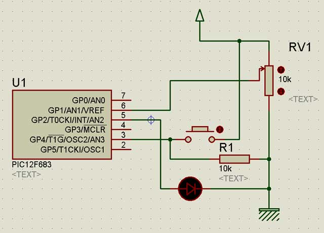
Im using this schematic:
Im using a recently charged Li-Ion (3.635v measured under load using a good multimeter) all is mounted in a protoboard
Using my last posted code the LED flickers, if I press the button it goes steady
Thanks!
Last edited by peu; - 7th May 2007 at 02:37.
mmm, yeah it works.. but a scope attach to show few glitches... mine too.
Deeper analysis show that flicker go away if i don't turn off the PWM off before updating the duty cycle. So maybe i have those latest silicon version.. and why the datasheet no longer suggest to turn off the PWM module...
aarrrggghh
Steve
It's not a bug, it's a random feature.
There's no problem, only learning opportunities.
let me join your ARGHHH...
Thanks Steve, at least now I know Im not alone here
I ordered some 12f683 samples not so long ago, if they changed something I guess I could test it with a rather new IC. But they are at my office, will check tomorrow if time allows.
Thanks for the continued help guys!
Pablo
in my code just remove the following line
and also that oneCode:CCP1CON = PWM_OFF
In darrel's include, comment out line 160Code:CCP1CON = CCP1CON | PWM_ON
At least, it work here.. thanks to my scopeCode:MOVE?CB 0, CCP1CON
Now the history don't tell if this will work with ALL PIC #, and with ALL silicone release. Time will tell.
Last edited by mister_e; - 7th May 2007 at 03:11.
Steve
It's not a bug, it's a random feature.
There's no problem, only learning opportunities.
You are a genius Mister_e. Wish I was as smart.
Don't give up, maybe one day you'll be. Then i could hire you
Steve
It's not a bug, it's a random feature.
There's no problem, only learning opportunities.
I removed that line from Darrel code and its clearly more stable now, but it still flickers at the lower range of the pot... very strange...
I just modified the code I posted to write to eeprom the lowest pot setting where its stable, the read value was from $007B to $007C but I recorded a couple of $007F and $0068 after 125 readings/writes, my guess for these oscillations was someting in the write cycle because after I stopped reading the led went to steady again, I wish I had a scope...
modified code:
Code:if calibrapin=1 then if conta < 250 then write conta, pote.byte1 write conta+1, pote.byte0 conta=conta+2 endif endif
Pablo
Strange indeed.
Well, I've made the changes Steve found and posted it at the same link.
I won't get my scope back till wednesday. (should have waited)
But I'll sure have a good look at it then.
<br>
DT
mmm, could be a noisy pot as well... using your code and on many low-value ADC.. they are all stable.. no noise, no frlicker.
what happen if you stick a 0.1 uF in parallel with your POT wiper?
Any 0.1uF + 10uF capacitor close to your PIC?
Steve
It's not a bug, it's a random feature.
There's no problem, only learning opportunities.
 Members who have read this thread : 2
You do not have permission to view the list of names.
 Posting Permissions


Bookmarks