12F683 Light Dimmer Problem (SOLVED)


Closed Thread
Results 1 to 20 of 20
  1. #1
    Join Date
    Jan 2008
    Location
    Pennsylvania
    Posts
    113

    Default 12F683 Light Dimmer Problem (SOLVED)

    Howdy.... I've been trying to get a light dimmer working now for about a week. I did a good bit of reading about using a triac and zero cross over detector prior to taking on this project but I'm stuck
    I believe I have all the correct code and can see on my scope things look good I'm including a picture.
    What we see here on the scope is the 120vac wave along with my trigger output based on getting triggered at the zero crossover point.

    Name:  scope.jpg
Views: 1560
Size:  31.1 KB

    I'm using INT on the 12F683 and on interrupt to detect the zero crossover from an H11AA1 and then triggering a pulse out for 1500 microseconds which you can see here. So far so good this looked great to me. I am feeding this pulse to an MOC3011M in turn using the MOC3011M to trigger the gate on a BT136/BT137 (I've tried both) however even though I am only feeding what looks like an "On" pulse for 1500 microseconds the bulb appears full on no matter what I do. The logic in the on interrupt routine is pretty basic for the time being.
    light=1
    pauseus 1500
    light=0

    I'm beginning to think that the triacs I have chosen. Any ideas what type of triac I should be using if someone out there has successfully gotten this to work. If anyone has any thoughts and/or would like to see my code and schematic if they think this will help I can upload those. I'm not sure if it is my programming or schematic since I am getting a good interrupt triggering pretty much dead on the zero crossing and in turn able to turn on an output for a period of time at that zero cross over point.
    Regards
    David

  2. #2
    Join Date
    Nov 2005
    Location
    Bombay, India
    Posts
    947


    Did you find this post helpful? Yes | No

    Default Re: 12F683 Light Dimmer Problem

    Try this way.

    1. The zero crossing is where the triac turns off.

    2. You need the period between 2 zero crossings to decide the time after the zero crossing you need to turn ON the triac

    3. Depending on the amount of power you need to output, you need to turn on the triac that much earlier than the zero crossing.

    The period is 10mS for a half period of 50Hz,
    if you need 50% power, you need to turn on your triac 5mS after the zero crossing.
    if you need 25% power, you will turn on the triac 10-2.5ms = 7.5mS after the zero crossing.
    for 10% power, you will turn on the triac 10-1mS = 9mS after the zero crossing.

    I hope I was able to communicate clearly without using a diagram.

    Cheers

  3. #3
    Join Date
    Jan 2008
    Location
    Pennsylvania
    Posts
    113


    Did you find this post helpful? Yes | No

    Default Re: 12F683 Light Dimmer Problem

    Chris, I believe I understand your explanation I picture the diagram perfectly in my head no need for it and it makes perfect sense now. Let me give that a go. I am running at 60hz so my half cycle time period would be 8.33mS
    So for half power I would turn on 4.16mS after zero crossing, 25% 6.25mS after zero crossing and 10% would be 7.49mS after zero crossing. Sound about right?
    Regards
    David

  4. #4


    Did you find this post helpful? Yes | No

    Default Re: 12F683 Light Dimmer Problem

    what are you using to vary the phase angle 0 to 8.3 ms after zero cross.... pot?

    are you also starting a timer at zero cross which triggers timer turnover interrupt that determines the delay 0 to 8.3ms for 0 to 100% phase?
    Last edited by amgen; - 3rd July 2020 at 02:02.

  5. #5
    Join Date
    Feb 2013
    Location
    Quebec, Canada
    Posts
    67


    Did you find this post helpful? Yes | No

    Default Re: 12F683 Light Dimmer Problem

    When a SCR is triggered it stays ON until the current drop to zero. TRIACs are 2 SCR doing a "69" to conduct both ways (AC).

  6. #6
    Join Date
    Jan 2008
    Location
    Pennsylvania
    Posts
    113


    Did you find this post helpful? Yes | No

    Default Re: 12F683 Light Dimmer Problem

    Hi guys got it to work. I am using an H11AA1 to detect the zero cross on the INT pin of the 12F673. From there I am using pauseus to hold the output pin off for x amount of microseconds. After the pause I turn on output pin which is driving an MOC3011 which in turn triggers the gate on the BT136. It is working quite well. I am not using a pot or anything to vary the delay. I want the light bulb to slowly brighten and then slowly dim for a lighthouse project.

    I will upload the program I did once I clean up all the commented code I left in there while I was working on this. (probably clean that up tomorrow) in the meantime here it is operating

  7. #7
    Join Date
    Nov 2005
    Location
    Bombay, India
    Posts
    947


    Did you find this post helpful? Yes | No

    Default Re: 12F683 Light Dimmer Problem

    Good work. Nice demo

  8. #8
    Join Date
    Jan 2008
    Location
    Pennsylvania
    Posts
    113


    Did you find this post helpful? Yes | No

    Default Re: 12F683 Light Dimmer Problem

    Thanks... sorry I called you Chris before I saw "Chris" instead of "Cheers" hahaha Anyway thanks.... I've got to clean up the code yet and draw up the schematic. Hopefully I will have some time later today to do that. Holiday weekend coming up so getting ready for that. I did add a little switch my father in law can switch and if he does the light will blink out "We love you dad" in morse code. I wanted it to say "Happy fathers day" but my wife vetoed that and said the latter. Bit late on fathers day I know but I got busy and had to order some of the components and they did not come in as fast as I needed them. I went back and reviewed some of the information I read about varying the phase and you are for sure right not sure how/why I got that backwards. Pretty cool little project does 60w lamp without getting warm using 1/2 watt resistors. I'm going to tweak those up to 1watt just in case. If you hold the 60w bulb on the on resistor gets just a tad warm but nothing you can't touch. 60w is going to be to bright for a little lighthouse but you never know with my father in law. I'll upload the code and schematic as soon as I have them done.

    P.S. the 12F683 was not that bad to work with getting the INT pin set up. Actually got it right the first time. I had been running at 8mhz but no need took it back down to default 4mhz. There was no need to go 8mhz and use any extra power on it. I'm trying to conserve all I can I want this to run with a https://www.mouser.com/ProductDetail/490-PBO-1-S5 by my calculations 200ma should be more than enough for this and the other components without getting anything warm. I did not put it on there yet but hopefully will get to that today and test it out. I need to make this simple for my father in law just plug and play without external wall wart.

    Regards
    David
    Last edited by DavyJones; - 3rd July 2020 at 13:10.

  9. #9
    Join Date
    Jan 2008
    Location
    Pennsylvania
    Posts
    113


    Did you find this post helpful? Yes | No

    Default Re: 12F683 Light Dimmer Problem

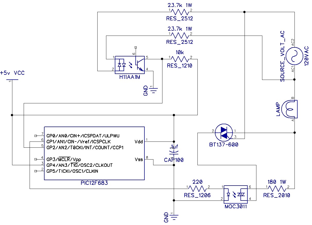
    Sorry this took longer than expected. Hopefully I did not make any mistakes creating the schematic after the fact but I am pretty sure I did not. I'm using diptrace to produce the schematic and I've only used it a few times. Here is the picture of my schematic and code. This is working really good I've had it on for several days and have not seen anything going wrong however I am open to suggestions/criticism if anyone spots anything and wants to comment please feel free.
    Regards
    David

    Code:
        ' LightHouse Lamp dimmer
        ' ======================
        '
        ' File name : Lighthousemorse.pbp
        ' Programmer : David C. Bittner
        ' Date : 2020-07-02
        ' Device : PIC12F683
        '
        ' This program is use to dim intensity of an AC line load
        ' like lamp, motor and other.  Developped for 60 Hz line.
             '
        ' The software need :
        '     1. A full wave signal from the AC line on GP2/INT
        '
    TRISIO = %00101101        ' All input except GP1 GP4  GP1 out to TRIAC
    OPTION_REG.7=0            ' Enable pull-ups
    OPTION_REG.6=1            ' Interupt on rise
    CMCON0 = 7                ' Disable analog comparator
    ANSEL=0                   ' Disable analog converter
    Triac  var GPIO.1 ' Output to TRIAC gate
    ACLine var GPIO.2 ' Input for the FullWave rectify AC line
    morse  var GPIO.5 ' used to check switch if 1 operate as dimmer, 0=morse out
    outp   var GPIO.4
        '
        '        Variable definitions
        '        ===================+    
        '
    TriacDelay var Word
    counter var word
    timercount var word
    updown var bit
    unit var word
    counter=0
    unit = 500
    
    TRIAC=1  'TEST TO MAKE SURE LIGHT COMES ON
    PAUSE 1000  'LEAVE IT ON FOR 1 SECONDS
    triac=0
    pause 5000   ' wait 5 seconds before starting
    triacdelay=8000
    ON INTERRUPT GOTO ACDetect
    INTCON=%10010000 ' Enable interrupt on GP2/INT change
    
    updown=1       '1=dim to bright, 0=bright to dim
    start: 
       '
       ' do what we need to in this routine if more
       '
       if morse=1 then
          triac=1
          outp=1
       else
          outp=0
          triac=0
          gosub morsecode
       endif
    goto start
    morsecode:
         pause 2000
         triac=1     ' W
         pause 400   'dot 
         triac=0
         
         pause 400
         triac=1
         pause 850   'dash
         triac=0
         
         pause 400
         triac=1
         pause 850   'dash
         triac=0
         
         pause 800
         triac=1     'E
         pause 400   'dot
         triac=0
         
    return    '
        '       ACDetect
        '       --------
        '
        ' Interrupt routine called by ACLine (GP2/INT) pin state change
        '
    disable
    ACDetect:
        'pauseus 240
        counter=counter+1
        if counter==5 then
            counter=0
            if updown==1 then
                triacdelay=triacdelay-100
                if triacdelay==-100 then
                    'triacdelay=8000
                    updown=0
                endif
            endif 
            if updown==0 then
                triacdelay=triacdelay+100
                if triacdelay==8100 then
                    updown=1
                endif
            endif 
        endif
        triac=0    
        pauseus triacdelay
    INTCON.1=0
    resume
    enable
    Attachment 8898
    Name:  Lighthouse.jpg
Views: 1417
Size:  128.6 KB
    Last edited by DavyJones; - 7th July 2020 at 14:41. Reason: wrong picture

  10. #10
    Join Date
    Jan 2008
    Location
    Pennsylvania
    Posts
    113


    Did you find this post helpful? Yes | No

    Default Re: 12F683 Light Dimmer Problem

    Can one of the mods change the title thread from "12F683 Light Dimmer Problem" to "12F683 Light Dimmer Problem (Solved)" I think that would be appropriate. Not sure if you can or not.
    Regards
    David

  11. #11
    Join Date
    Jan 2008
    Location
    Pennsylvania
    Posts
    113


    Did you find this post helpful? Yes | No

    Default Re: 12F683 Light Dimmer Problem (SOLVED)

    thank you
    David

  12. #12
    Join Date
    Jan 2008
    Location
    Pennsylvania
    Posts
    113


    Did you find this post helpful? Yes | No

    Default Re: 12F683 Light Dimmer Problem (SOLVED)

    So sorry on the original schematic I had the gate on the triac on the wrong pin. The gate is on pin 3 not pin 2
    Name:  Lighthouse.jpg
Views: 1397
Size:  128.5 KB

    David
    Attached Images Attached Images  
    Last edited by Ioannis; - 7th July 2020 at 23:23.

  13. #13
    Join Date
    Nov 2003
    Location
    Greece
    Posts
    3,793


    Did you find this post helpful? Yes | No

    Default Re: 12F683 Light Dimmer Problem (SOLVED)

    I see you have corrected the image, right?

    Ioannis

  14. #14
    Join Date
    Jan 2008
    Location
    Pennsylvania
    Posts
    113


    Did you find this post helpful? Yes | No

    Default Re: 12F683 Light Dimmer Problem (SOLVED)

    yes I corrected it and had to upload it again.

  15. #15
    Join Date
    Nov 2005
    Location
    Bombay, India
    Posts
    947


    Did you find this post helpful? Yes | No

    Default Re: 12F683 Light Dimmer Problem (SOLVED)

    CAP100 is showing the wrong polarity.

  16. #16
    Join Date
    Nov 2003
    Location
    Greece
    Posts
    3,793


    Did you find this post helpful? Yes | No

    Default Re: 12F683 Light Dimmer Problem (SOLVED)

    Nice catch Jerson!

    Ioannis

  17. #17
    Join Date
    Jan 2008
    Location
    Pennsylvania
    Posts
    113


    Did you find this post helpful? Yes | No

    Default Re: 12F683 Light Dimmer Problem (SOLVED)

    Sorry about that strangely I could not find a non-polarized cap symbol and choose that one and forgot to flip it. Let me search in the program some more to see if I can find a non-polarized one. There are so many symbols mostly based on part numbers. Hard to find just general symbols.
    David

    I found one finally it's not in the CAP category either. thanks for catching that.

    Name:  Lighthouse.jpg
Views: 1732
Size:  128.2 KB
    Last edited by DavyJones; - 8th July 2020 at 12:45.

  18. #18
    Join Date
    Jan 2008
    Location
    Pennsylvania
    Posts
    113


    Did you find this post helpful? Yes | No

    Default Re: 12F683 Light Dimmer Problem (SOLVED)

    Circuit boards are in. I realize that this differs slightly from my schematic I uploaded. I added a PBO-1-S5 to the board to supply power and eliminate the need for a wall wart for power. The PBO is really small and supplies 5v and 200ma which by my calculations is more than enough for this project. Also there are a few extra components on here which were added as the recommended filtering for the PBO. C1, C2 and C3 could have been SMD and L1 but they were out of stock so I went with conventional cap's,inductor for this version. The 12F683 can be SMD too but I choose a socket so I can mess around with the code and swapping out the processor quickly. The other thing I messed up on was for AC-in and Light I wanted to use 2 up terminal blocks but wasn't paying attention when I laid those out so they won't fit without running into the other components so for this version I will solder directly to the board the AC-in and light. I do notice every once in a while as the light dims and get's brighter there is a slight "glitch" for a microsecond the bulb will blink. It is so random and slight unless you are staring right at the bulb it's unnoticeable. It's almost as if there was a spike on the AC but since it happens so infrequently I don't think I could catch this on my scope to see if that is what it is or something else. Once I put this together and do some testing I was going to modify my schematic to include the PBO and extra components used for the power section. If anyone is interested let me know I will re-up the schematic

    David

    Name:  circuit board.jpg
Views: 1253
Size:  55.9 KB

  19. #19
    Join Date
    Oct 2005
    Location
    Sweden
    Posts
    3,516


    Did you find this post helpful? Yes | No

    Default Re: 12F683 Light Dimmer Problem (SOLVED)

    You might know exactly what you're doing and if so that's great but just in case you don't here are some comments meant in all friendlyness:

    You're dealing with mains voltages here so you need think a bit about clearance and creepage distances between the two nodes (phase/neutral) of the mains itself AND between the mains and the low voltage section.

    It looks like you're running phase and neutral REALLY (really!) close together and close to pins 5 and 7 on the AC/DC module (up along the right hand side of the board as shown in the photo) and also REALLY close to the output of the AC/DC module (I'm talking specifically about the pad for L1 which I'm guessing is the series inductor on the output).

    There's a reason there's 0.2" between pins on the mains side and then 0.3" between pins OF the mains side and the secondary side of the AC/DC module. By then having pins/pads of components connected to the mains side in close proximity of pins/pads connected to secondary side you're throwing that nice isolation that the AC/DC module provides out the window.

    Yes, there' soldermask on the traces and it helps but still, I would not feel comfortable with that - especially if I were to hand it over to someone else - friend or not :-)

    Again, all meant in a friendly way!

    /Henrik.

  20. #20
    Join Date
    Jan 2008
    Location
    Pennsylvania
    Posts
    113


    Did you find this post helpful? Yes | No

    Default Re: 12F683 Light Dimmer Problem (SOLVED)

    Henrik, Thank you. You make very good points here. this is version one and I did not worry about some of those distances. In v2.0 I will take into account your suggestions to properly space the AC. I crammed things close together not taking that into account so the board would fit into the box I had on hand. I'm going to take your advice on my next one and design it first then find a box it will fit nicely into. I did solder all the components on there and it does work however as you pointed out there are a few things I need to consider.
    I appreciate the feedback.

Similar Threads

  1. Light dimmer not working
    By Normnet in forum mel PIC BASIC Pro
    Replies: 8
    Last Post: - 13th January 2013, 18:26
  2. Light dimmer problem
    By FromTheCockpit in forum mel PIC BASIC Pro
    Replies: 12
    Last Post: - 9th July 2012, 13:36
  3. Replies: 12
    Last Post: - 16th May 2011, 00:06
  4. 12F683 GPIO.3 problem
    By ozarkshermit in forum mel PIC BASIC Pro
    Replies: 7
    Last Post: - 30th October 2009, 09:43
  5. 50hz sync for light dimmer
    By tirithen in forum General
    Replies: 2
    Last Post: - 6th September 2008, 20:29

Members who have read this thread : 1

You do not have permission to view the list of names.

Tags for this Thread

Posting Permissions

  • You may not post new threads
  • You may not post replies
  • You may not post attachments
  • You may not edit your posts