Battery power back-uped circuit


Closed Thread
Results 1 to 29 of 29
  1. #1
    Join Date
    Aug 2006
    Location
    SWITZERLAND (french speaking)
    Posts
    891

    Default Battery power back-uped circuit

    Hello All,

    I'm making GSM alarm controller using a SIM800L GSM chip from SIMCOM.

    Since the project is about "monitoring" and "alarming", it is important ton ensure a redundant power feeding (= LiPo battery).

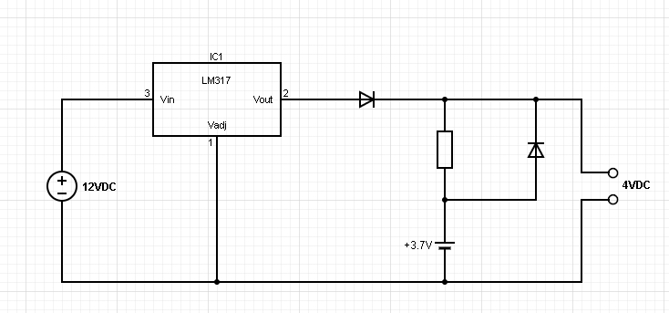
    The module supports 3.4 to 4.4 VDC and I would imagine to go for 4VDC (my imagination - will depend on circuit design). For info, this chip draws up to 2 Amps when bursts occur (!) but draws around 40mA in idle state.

    I've read some threats about "oring" DC power sources (with Schottky diodes or so) but here I don't know how to achieve a correct circuit since I'll be using a rechargeable battery (not like a battery for an RTC).

    My points are:
    - is the schema here under or something looking like "possible" at all?
    - the LiPo 3.7V cell will need to be charged (or not!) after a +/- long main voltage supply (i.e. 12VDC) supply but how is it possible since it is connected in parallel with another circuit
    - if there is already something "out there", can anyone point me to a link please?

    Thanks for any info

    Name:  Batt Backup Power.jpg
Views: 2430
Size:  102.9 KB
    Roger

  2. #2
    Join Date
    May 2013
    Location
    australia
    Posts
    2,379


    Did you find this post helpful? Yes | No

    Default Re: Battery power back-uped circuit

    if you charge lipo batteries incorrectly there is a substantial fire risk, drawing power from the charging cct can lead to improper charging.
    you might like this
    http://ww1.microchip.com/downloads/e...tes/01149c.pdf
    Warning I'm not a teacher

  3. #3
    Join Date
    Aug 2006
    Location
    SWITZERLAND (french speaking)
    Posts
    891


    Did you find this post helpful? Yes | No

    Default Re: Battery power back-uped circuit

    Thanks Richard,

    That was really quick!!!

    Yup, I think this is exactly what I'm looking for.

    I should have thought about these chips since I sometimes use MCP73831 ones.

    Thanks a lot again
    Roger

  4. #4
    Join Date
    Jan 2006
    Location
    Istanbul
    Posts
    1,185


    Did you find this post helpful? Yes | No

    Default Re: Battery power back-uped circuit

    Quote Originally Posted by richard View Post
    if you charge lipo batteries incorrectly there is a substantial fire risk, drawing power from the charging cct can lead to improper charging.
    you might like this....

    As Richard pointed out risk of fire, you may want to consider Li-fepo4 batteries.
    Almost no risk of fire under high heat, short circuit or over charging ...

    But they are 3.2 Volts.
    "If the Earth were a single state, Istanbul would be its capital." Napoleon Bonaparte

  5. #5
    Join Date
    Aug 2006
    Location
    SWITZERLAND (french speaking)
    Posts
    891


    Did you find this post helpful? Yes | No

    Default Re: Battery power back-uped circuit

    Thanks Sayser,

    Unfortunately, 3.2V will be too low - anyway, thanks for the Li-FePo4 advice

    Name:  000223.png
Views: 1845
Size:  40.6 KB
    BTW, going back to AN1149 and the choice of the P-Channel MOSFET, as I don't know if a FDN360P will do the job?
    Name:  000225.png
Views: 1633
Size:  115.5 KB
    Any clue?
    Roger

  6. #6
    Join Date
    Jan 2006
    Location
    Istanbul
    Posts
    1,185


    Did you find this post helpful? Yes | No

    Default Re: Battery power back-uped circuit

    Consider this one: DMP3099L-7

    I have my own charging circuit controlled by PIC with FVR.
    Measure batt voltage by adc read on FVR to calculate the batt voltage.
    If over 4.25V then cut the charge; if lower than 2.75V then suspend all operations.
    All done within the pic.

    You need an ppnTR-P-ch charging circuit; very simple.
    "If the Earth were a single state, Istanbul would be its capital." Napoleon Bonaparte

  7. #7
    Join Date
    Nov 2003
    Location
    Greece
    Posts
    3,793


    Did you find this post helpful? Yes | No

    Default Re: Battery power back-uped circuit

    FVR is not at all accurate, so that 4.25... I doubt you are safe.

    Ioannis
    Last edited by Ioannis; - 19th May 2020 at 10:58.

  8. #8
    Join Date
    Nov 2003
    Location
    Greece
    Posts
    3,793


    Did you find this post helpful? Yes | No

    Default Re: Battery power back-uped circuit

    Roger, the minus Vgth is correct. Consider it a different visual angle!

    In P-channel or PNP transistor the voltages are the opposite of the N-channel or NPN transistors. Means that the voltage og the gate in respect to the source is negative. The key to understand here is the term "in respect".

    Ioannis

  9. #9
    Join Date
    Aug 2006
    Location
    SWITZERLAND (french speaking)
    Posts
    891


    Did you find this post helpful? Yes | No

    Default Re: Battery power back-uped circuit

    If I may ask further,

    The "most important" value to take care off is the "Gate Threshold Voltage"; right?

    It has to be as low as possible...but how low and why?

    Name:  001347.jpg
Views: 1379
Size:  251.8 KB

    I thought RDSon value is very important too. But in this case, where the current is somehow small, is this less important in choosing the "right" MOSFET?
    Roger

  10. #10
    Join Date
    Jan 2006
    Location
    Istanbul
    Posts
    1,185


    Did you find this post helpful? Yes | No

    Default Re: Battery power back-uped circuit

    Quote Originally Posted by Ioannis View Post
    FVR is not at accurate, so that 4.25... I doubt you are safe.

    Ioannis


    Why is not not accurate?
    I get 1.024V with 1x output.
    And if the Vdd is 2,5V I still have 1.024V at my FVR output. I never encountered an accuracy issue.

    But, if you have a high freq circuity on the same pcb, or even if your PWM module is running, then I agree, FVR can be disrupted.
    Also, here is a simple circuit diagram for NPN-PCH charging. Assuming you are not charging the batt with high amps, LM317 would do the job. If not, change LM317 to a switching circuit to have higher efficiency and lower heat.


    Name:  2020-05-19 11_58_13-pchcharge - Proteus 8 Professional - Schematic Capture.png
Views: 1895
Size:  22.0 KB
    "If the Earth were a single state, Istanbul would be its capital." Napoleon Bonaparte

  11. #11
    Join Date
    Nov 2003
    Location
    Greece
    Posts
    3,793


    Did you find this post helpful? Yes | No

    Default Re: Battery power back-uped circuit

    Because according to Electrical Specs, the FVR may be from -8% to +6% for example on 16F1827.

    I would not trust this to charge a LiPo battery at all!

    Ioannis

  12. #12
    Join Date
    Nov 2003
    Location
    Greece
    Posts
    3,793


    Did you find this post helpful? Yes | No

    Default Re: Battery power back-uped circuit

    Roger,

    The important specs is dependent on the application.

    For example, if you drive the MosFet from a logic level chip, say a MCU, then you want the Vgs to be as low as possible for the MosFet to be fully closed and have minimum Rdson

    Other spec like the circuit on the above Note, is the Rds itself, so you don't have thermal losses.

    Also the Vds max should be more than the worst case on your circuit voltage levels.

    Ioannis

  13. #13
    Join Date
    Aug 2006
    Location
    SWITZERLAND (french speaking)
    Posts
    891


    Did you find this post helpful? Yes | No

    Default Re: Battery power back-uped circuit

    Quote Originally Posted by Ioannis View Post
    Roger,
    The important specs is dependent on the application.....
    Ioannis
    Thanks Ioannis.

    I'll give it a try with a few different MOSFETs and see what happens.

    For any reason, until I haven't tested it with my "hands" (and the voltmeter ), it doesn't get inside my head that easy.

    Maybe I'm getting too old to play with all these fantastic toys
    Roger

  14. #14
    Join Date
    Nov 2003
    Location
    Greece
    Posts
    3,793


    Did you find this post helpful? Yes | No

    Default Re: Battery power back-uped circuit

    Experience is gained only in action!

    Ioannis

  15. #15
    Join Date
    Jan 2006
    Location
    Istanbul
    Posts
    1,185


    Did you find this post helpful? Yes | No

    Default Re: Battery power back-uped circuit

    Quote Originally Posted by Ioannis View Post
    Experience is gained only in action!

    Ioannis
    This statement is giving me naughty thoughts
    "If the Earth were a single state, Istanbul would be its capital." Napoleon Bonaparte

  16. #16
    Join Date
    Nov 2003
    Location
    Greece
    Posts
    3,793


    Did you find this post helpful? Yes | No

    Default Re: Battery power back-uped circuit

    You got yourself 2 points so far with naughty thoughts!

    Ioannis

  17. #17
    Join Date
    May 2004
    Location
    NW France
    Posts
    3,611


    Did you find this post helpful? Yes | No

    Default Re: Battery power back-uped circuit

    Hello, Flotul,

    LiPo batts are somewhat tricky to use ...

    I suggest you to use something called " BMS " with your battery ... it's a device that cares with every problem that could occur : Overchage, under voltage, load shorted ...

    that can avoid fire or exploding the battery ... not negligible !

    https://www.nkon.nl/fr/accessories/1...2mos-5530.html for example ...

    Alain
    ************************************************** ***********************
    Why insist on using 32 Bits when you're not even able to deal with the first 8 ones ??? ehhhhhh ...
    ************************************************** ***********************
    IF there is the word "Problem" in your question ...
    certainly the answer is " RTFM " or " RTFDataSheet " !!!
    *****************************************
  18. #18
    Join Date
    Aug 2006
    Location
    SWITZERLAND (french speaking)
    Posts
    891


    Did you find this post helpful? Yes | No

    Default Battery power back-uped circuit

    Hi Alain,

    I thought these BMS circuits were already interated in the batteries?

    When I look to one of my LiPo battery, I can see some kind of a circuit at the top of it.

    I might be wrong, but I think this is a protection circuit (difficult to see okay, but believe me, there is a small circuit here ) or isn't it?

    Name:  IMG_20200601_195052.jpg
Views: 1355
Size:  19.8 KB
    Roger

  19. #19
    Join Date
    May 2004
    Location
    NW France
    Posts
    3,611


    Did you find this post helpful? Yes | No

    Default Re: Battery power back-uped circuit

    Hi, Flotul,

    Those BMS are not always installed ...

    I have dozens of LiPo / LiFe batts home and only one has it included ... so, consider it's not mandatory !!!

    sometimes, there's only a fuse !!!

    Alain
    ************************************************** ***********************
    Why insist on using 32 Bits when you're not even able to deal with the first 8 ones ??? ehhhhhh ...
    ************************************************** ***********************
    IF there is the word "Problem" in your question ...
    certainly the answer is " RTFM " or " RTFDataSheet " !!!
    *****************************************

  20. #20
    Join Date
    May 2013
    Location
    australia
    Posts
    2,379


    Did you find this post helpful? Yes | No

    Default Re: Battery power back-uped circuit

    my experience to date is that the bms is far more likely to fail before the battery and that it will then do its best to destroy the battery utterly.
    i have had good success in removing failed bms modules to discover perfectly good batteries . better bms modules are cheap and plentiful.
    just because they won't take a charge is not always a dead battery
    Last edited by richard; - 2nd June 2020 at 12:43.
    Warning I'm not a teacher

  21. #21
    Join Date
    Jan 2006
    Location
    Istanbul
    Posts
    1,185


    Did you find this post helpful? Yes | No

    Default Re: Battery power back-uped circuit

    Quote Originally Posted by Acetronics2 View Post
    Hi, Flotul,

    Those BMS are not always installed ...

    I have dozens of LiPo / LiFe batts home and only one has it included ... so, consider it's not mandatory !!!

    sometimes, there's only a fuse !!!

    Alain

    I agree with this.

    When we order batts, there is option having it with the protection; As it is an option and if you have a smart charging circuit, then it just additional cost which I think is unnecessary.

    The ones with the protectioın we received have higher failure return rate than those without the protection. Circuit burns out eventhough there is nothing wrong with the charging.
    "If the Earth were a single state, Istanbul would be its capital." Napoleon Bonaparte

  22. #22
    Join Date
    Nov 2003
    Location
    Greece
    Posts
    3,793


    Did you find this post helpful? Yes | No

    Default Re: Battery power back-uped circuit

    Lithium batts should be under surveillance either charging or discharging.

    The little circuits are supposed to work in either case, not allowing overcharge or flat discharge the batteries. The second is important as many devices continue to drain the batteries to very low levels, finally destroying them.

    It is really annoying that the protection circuits fail...

    Ioannis

  23. #23
    Join Date
    Aug 2006
    Location
    SWITZERLAND (french speaking)
    Posts
    891


    Did you find this post helpful? Yes | No

    Default Let's build it!

    Hi All,

    I'm now (finally...) building my project and its about time to order the missing components to have something to play with (without any reference to naughty thoughts ).

    So, here's the circuit I'm building:
    Name:  Power SIM7600 backup.jpg
Views: 775
Size:  94.7 KB

    Reading the (very interesting) MicroChip's AN1149 about battery charge and power backup, I can see that a particular attention is to be paid to the choice of the Q1's (the P-Mosfet) where a "proper" Vgs(th) has to be chosen.

    Unfortunately, I'm not an electronician, just an electrician creating himself (lots of) problems with this PIC stuff = I don't know how to calculate or determine with exactitude how to dimension the needed P-chanel Mosfet

    Can anyone help me out and suggest a component (according to the DS, a combined S-diode and Mosfet is nice) or the Vgs(th) value I will have to find to make my circuit work? Instead, I would appreciate someone explain me how to "calculate" this Vgs(th) I'll need....
    Roger

  24. #24
    Join Date
    Aug 2006
    Location
    SWITZERLAND (french speaking)
    Posts
    891


    Did you find this post helpful? Yes | No

    Default Re: Let's build it!

    BTW, I don't think the above schema will work.

    Is this really correct?
    Name:  Power SIM7600 backup 2.jpg
Views: 785
Size:  98.0 KB


    Shouldn't it be something more like this?
    Name:  Power SIM7600 backup 3.jpg
Views: 764
Size:  98.2 KB
    Last edited by flotulopex; - 11th February 2021 at 15:37.
    Roger

  25. #25
    Join Date
    Sep 2009
    Posts
    737


    Did you find this post helpful? Yes | No

    Default Re: Battery power back-uped circuit

    First schematic can work. But MOSFET have no purpose. There is no need for one.
    Second schematic doesn't allow battery discharge when charging.
    Don't know where you found that schematic, but look at
    http://ww1.microchip.com/downloads/e...tes/01149c.pdf
    Page 2.

  26. #26
    Join Date
    Aug 2006
    Location
    SWITZERLAND (french speaking)
    Posts
    891


    Did you find this post helpful? Yes | No

    Default Re: Battery power back-uped circuit

    Thanks pedja,

    The schemas come from this exact document you refer to in your last post, adapted to DC supply.


    But MOSFET have no purpose. There is no need for one.
    Can you please explain?

    Without any "switch" (MOSFET in this cas, how I understand it), how would hte load be fed either by the main supply or the battery in case of main supply failure?
    Roger

  27. #27
    Join Date
    Sep 2009
    Posts
    737


    Did you find this post helpful? Yes | No

    Default Re: Battery power back-uped circuit

    You shorted gate to GND in first schematic. So MOSFET are allways on.
    As you see in document anodes of LEDs are connected to positive input supply via diode. Not to GND.
    I overlooked D1 in second schematic. So my explanation for not powering load while charging is not correct.
    But you must be careful with that schematic. As you can have 5.1V on output while charging. Then voltage will drop to 3.7V. You can't power modem from that. Not directly.
    I'll suggest that you power modem directly from battery, and rest of circuit via 3V LDO, or 2.8V. You can get it witht Iq less than 1uA.
    Then just build 1 or 2A 4.2V CC/CV charger for battery. I'll suggest that you use switch(step down), not linear charger.
    If you want to stick to microchip AN1149, then you need really good SEPIC power supply for modem(to get recommended 3.8V). Also modem must have low ESR capacitors near it.
    So not that trivial circuit to design.
    EDIT:
    SEPIC or some isolated topology is must, because you have higher input voltage when powering from AC, then output voltage(stepdown). But when you run it from battery you will have lower voltage on input then output.
    You could try some hot swap PSU with battery while modem running, but i think modem will restart...
    Last edited by pedja089; - 12th February 2021 at 00:17.

  28. #28
    Join Date
    Aug 2006
    Location
    SWITZERLAND (french speaking)
    Posts
    891


    Did you find this post helpful? Yes | No

    Default Re: Battery power back-uped circuit

    Thank you pedja,

    I'll give it a try with what I have in my drawer up to now.

    I still don't know what MOSFET I should choose....
    Roger

  29. #29
    Join Date
    Sep 2009
    Posts
    737


    Did you find this post helpful? Yes | No

    Default Re: Battery power back-uped circuit

    Mosfet is easy. Chose one with low Vgsth and as low as possible Rdson. Current more than 4A for modem only.
    I usually use AO3401. To be safe I put 2 parallel. Also it is good idea to PIC have control over them. SIM900D had sometimes issue where it would stop responding, and continue to work for months after power off on.
    So from then I always make modem PSU controled by PIC, and add discharge resistor. Sometimes I also make resistor PIC controlled, if it battery powered device.

Similar Threads

  1. How to detect low battery in battery powered F683 circuit
    By tekart in forum mel PIC BASIC Pro
    Replies: 31
    Last Post: - 21st May 2015, 19:20
  2. Auto power off back light with 16F84A
    By manojsoorya in forum FAQ - Frequently Asked Questions
    Replies: 1
    Last Post: - 12th April 2014, 15:14
  3. Back from 6 yrs away - best in circuit programmer/breadboard?
    By PickyPerson in forum mel PIC BASIC Pro
    Replies: 17
    Last Post: - 27th January 2012, 05:21
  4. 4.5V Battery charging circuit....
    By Megahertz in forum Schematics
    Replies: 2
    Last Post: - 2nd July 2010, 01:33
  5. Replies: 1
    Last Post: - 20th December 2005, 04:56

Members who have read this thread : 4

You do not have permission to view the list of names.

Posting Permissions

  • You may not post new threads
  • You may not post replies
  • You may not post attachments
  • You may not edit your posts