Circuit question


Closed Thread
Results 1 to 8 of 8

Hybrid View

  1. #1
    Join Date
    Jan 2008
    Location
    Sweden
    Posts
    187

    Default Circuit question

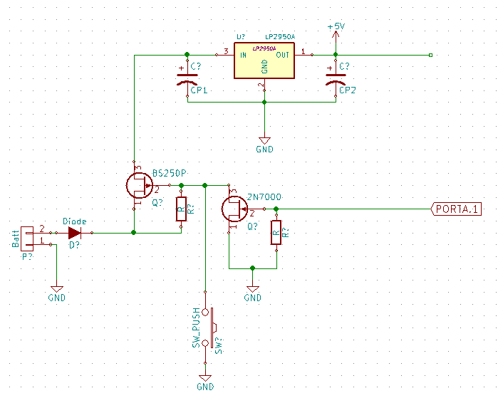
    I have A circuit that looks like this and all works as expected.

    But I´m not sure if the BS250 can handle the two capacitors i the long time, I assume that the BS250 will be shorted for a short time when the button is pressed and the C1 and C2 are empty?

    C1 - 1uF
    C2 - 2,2uF
    Power source - 9v battery

    Name:  cc.png
Views: 1169
Size:  12.0 KB

  2. #2
    Join Date
    Aug 2003
    Posts
    985


    Did you find this post helpful? Yes | No

    Default Re: Circuit question

    Pushing the button sends the gate low (BS250), but I don’t see how it directly shorts
    C1,C2, or anything else. R? prevents a direct short in any case as far as I can see.

  3. #3


    Did you find this post helpful? Yes | No

    Default Re: Circuit question

    looks to me like the pushbutton 'closes' the P channel fet , charges the caps and putting PortA1 high keeps circuit going until PortA1 goes low, BS250 opens and the caps drain.... ??

  4. #4
    Join Date
    Nov 2007
    Location
    West Covina, CA
    Posts
    219


    Did you find this post helpful? Yes | No

    Default Re: Circuit question

    I went here to see how much in-rush current you can expect and understand your concern about that BS250 part limited at 180mA. The data sheet doesn't even provide pulse current parameters.

    I would upgrade to a another P-CH FET with a much lower ON resistance in the low 100's of milli-Ohms that can easily handle the short burst for peace of mind.
    Louie

  5. #5
    Join Date
    Jan 2008
    Location
    Sweden
    Posts
    187


    Did you find this post helpful? Yes | No

    Default Re: Circuit question

    Quote Originally Posted by LinkMTech View Post
    I went here to see how much in-rush current you can expect and understand your concern about that BS250 part limited at 180mA. The data sheet doesn't even provide pulse current parameters.

    I would upgrade to a another P-CH FET with a much lower ON resistance in the low 100's of milli-Ohms that can easily handle the short burst for peace of mind.
    In this datasheet from the place I bought the part http://www.electrokit.com/productFile/download/4175
    it say´s something about "Pulsed Drain Current IDM =-3 A

    But I don't understand what they meaning with -3A?

  6. #6
    Join Date
    Nov 2007
    Location
    West Covina, CA
    Posts
    219


    Did you find this post helpful? Yes | No

    Default Re: Circuit question

    In short, it's the current leaving or supplied through the Drain as the case with the P channel. Electron flow verses Hole flow theory, depending on your upbringing.

    So the 3 Amp rating in the 300us pulse test is more than adequate since the initial cap charge of ~640mA is over very quickly, less than 40us, then tapers off from there.
    Louie

Similar Threads

  1. Question about the switch circuit in the PBP manual
    By schu4647 in forum mel PIC BASIC Pro
    Replies: 3
    Last Post: - 12th April 2010, 13:37
  2. Replies: 6
    Last Post: - 18th September 2009, 19:30
  3. Circuit Design Question
    By bradb in forum mel PIC BASIC Pro
    Replies: 6
    Last Post: - 11th August 2009, 08:18
  4. Short circuit portection circuit ?
    By iugmoh in forum Schematics
    Replies: 1
    Last Post: - 21st December 2008, 21:33
  5. Replies: 3
    Last Post: - 29th October 2006, 09:16

Members who have read this thread : 1

You do not have permission to view the list of names.

Posting Permissions

  • You may not post new threads
  • You may not post replies
  • You may not post attachments
  • You may not edit your posts