SPI SS Issue


Closed Thread
Results 1 to 2 of 2

Thread: SPI SS Issue

  1. #1
    Join Date
    Aug 2008
    Posts
    12

    Default SPI SS Issue

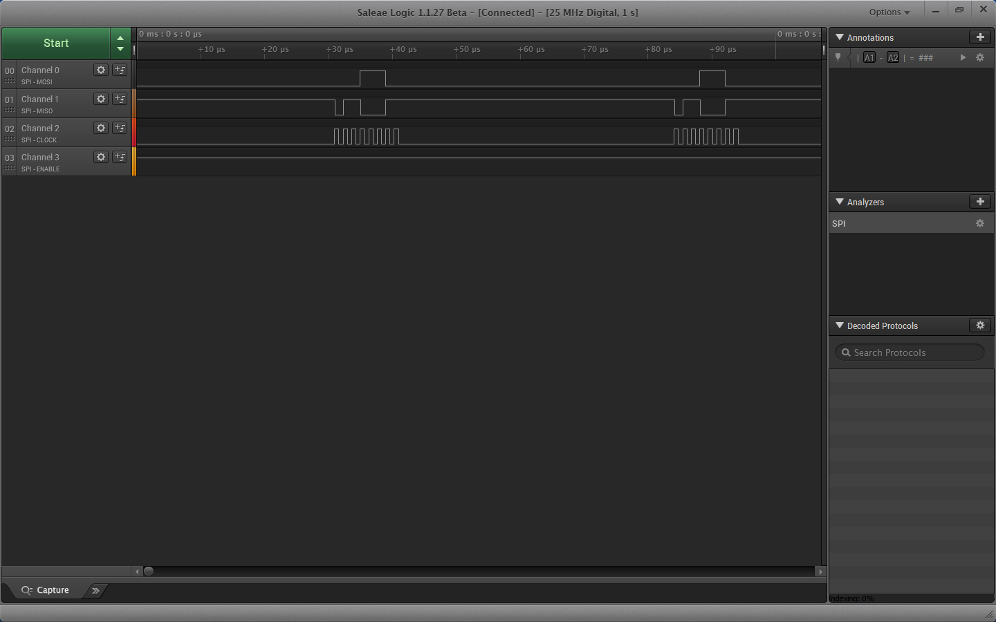
    I've got successful SPI communication between an 18F2550(master) and a 16F887(slave) with the slave SS pin enabled. Here is the code for my master and slave and an analyzer screenshot of successful communication with the master sending 28 and the slave returning 99, as expected:

    Name:  SPI.1.png
Views: 370
Size:  92.2 KB
    Code:
    'SPI MASTER CODE for 18F2550
    	
    DEFINE  OSC     20   
    
    pause 5000
    
    cs        VAR PORTB.7
    cs2      VAR PORTB.6
    SSPEN  VAR SSPCON1.5
    CKP     VAR SSPCON1.4
    SMP     VAR SSPSTAT.7
    CKE     VAR SSPSTAT.6
    BF       VAR SSPSTAT.0
    sig       VAR byte
    sig2     VAR byte
    
    TRISA = %11111111	' Set PORTA to all input
    TRISB = %00000001
    TRISC.7 = 0
    
    cs = 1
    cs2 = 1
    
    SSPEN = 1
    
    SSPCON1.0 = 0
    SSPCON1.1 = 1
    SSPCON1.2 = 0
    SSPCON1.3 = 0
    CKP = 0
    CKE = 0
    SMP = 0
    
    mainloop:
       
        cs = 0     
        SSPBUF = 28   
        while BF = 0 : wend
        sig = SSPBUF    
        cs = 1
        pauseus 100     
        goto mainloop           
       
    END
    Code:
    'SPI SLAVE CODE for 16F887
    
    DEFINE  OSC     20
    
    SSPEN   VAR SSPCON.5
    CKP      VAR SSPCON.4
    SMP      VAR SSPSTAT.7
    CKE      VAR SSPSTAT.6
    BF        VAR SSPSTAT.0
    
    TRISA = %11111111	
    TRISB = %11111111
    TRISC = %11011111
    TRISD = %00000000
    
    SSPCON = %00000100
    
    CKP = 0
    CKE = 0
    SMP = 0
    
    SSPEN = 1
    		
    mainloop:
       
        while BF=0: wend
        SSPBUF = 99    
        goto mainloop
           
    END
    The problem is that when I test this without dropping the SS line low to enable I still see the MISO transmission from my slave. I thought that if SS does not go low then the slave chip would not be enabled? Why would the slave respond even when its SS pin is high as seen in the screenshot below from my analyzer?

    It seems that my slave chip does not know it is in "SPI Slave mode, clock = SCK pin, SS pin control enabled". I'd like to work this out because when I add more slaves with their own SS lines from my master they all respond at the same time on the MISO line and the data is incorrect because they aren't individually enabling/disabling as expected.

    Any insight would be greatly appreciated.

    Name:  SPI.2.png
Views: 309
Size:  78.1 KB
    Last edited by Archangel; - 17th October 2014 at 03:01. Reason: code tags

  2. #2
    Join Date
    Aug 2008
    Posts
    12


    Did you find this post helpful? Yes | No

    Default Re: SPI SS Issue

    This has been solved. The issue was that on the PIC16F887, SS is on RA5 which is also AN4, and for that reason I had to write to a register to enable the digital input buffer because I am using that pin as a digital input. In this case it is ANSEL. It had to be cleared for that pin. Many thanks to Ric.

Similar Threads

  1. IF-THEN issue
    By jmgelba in forum mel PIC BASIC Pro
    Replies: 5
    Last Post: - 12th February 2014, 22:09
  2. Need to use SPI but I'm already using the SPI port
    By Christopher4187 in forum mel PIC BASIC Pro
    Replies: 13
    Last Post: - 30th December 2012, 09:52
  3. Code Issue - select case or 'if' issue - not sure why
    By jamie_s in forum mel PIC BASIC Pro
    Replies: 2
    Last Post: - 7th October 2007, 08:52
  4. SPI on a pic without hardware SPI?
    By modifyit in forum mel PIC BASIC Pro
    Replies: 3
    Last Post: - 26th April 2006, 13:29
  5. Help with timing issue
    By BertMan in forum mel PIC BASIC Pro
    Replies: 3
    Last Post: - 21st October 2005, 04:15

Members who have read this thread : 2

You do not have permission to view the list of names.

Posting Permissions

  • You may not post new threads
  • You may not post replies
  • You may not post attachments
  • You may not edit your posts