Hello, thank you for visiting the picbasic users forum. Just a little note to remind you that, if your have registeted for a user account and you have not logged in and posted a message, unused accounts are deleted from time to time.
We track user account usage. As part of our general maintenaince and to meet the GDPR requirments, we have elected to delete user accounts that are unused.
We define unused as:
NOT haveing ever posted a message on the forum
AND
NOT having logged in for more than 360 days.
If you find that your account is deleted, because of inactivity, you will need to contact the forum administrator to have the account re-instated. email: [email protected]


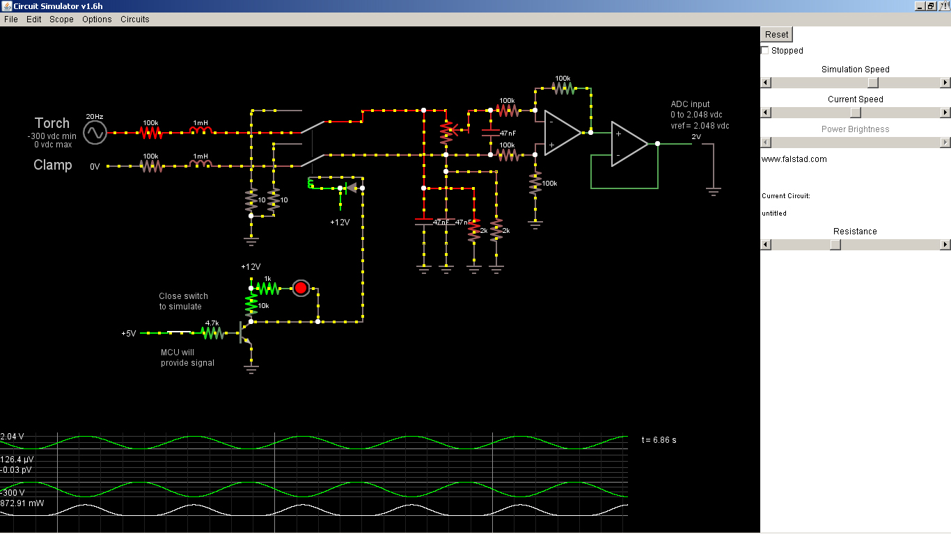


 All of the other THC's out there do it with a scaler (divider)... Oh boy, I'm baffled now!
 I do have to admit, it is self-serving too. Heck, I'll get a THC out of it too. Here's some progress of the PCB's ready to go to OSHPark. RS232 and 20x4 lcd display through the RJ-45 jacks up top. All menus and settings will be controlled through a 24 detent encoder with a built-in push switch. The scaler and gpio boards are set up as daughter boards to the main board as well. I guess I should breadboard the project, now that I have the PCB's done


Bookmarks