Drawing a blank on trigger pin polarity


Closed Thread
Results 1 to 5 of 5
  1. #1
    Join Date
    Jan 2010
    Posts
    88

    Default Drawing a blank on trigger pin polarity

    Hello,

    I currently am using a dual optocoupler to trigger an input on my pic. One LED is set to be a positive trigger while the other is set to be a negative trigger. They both pull one input on my pic to ground.

    I am trying to consolidate my components and wires to be just one wire. What I am seeking to do is have a wire that when left unconnected, will do nothing. If either a positive or negative is applied to this wire, then the input it is connected to will be triggered.

    I've seen other boards that use an input wire, but in order to select the trigger polarity, you must use jumpers.

    Thoughts that I came up with would be to use the AD input and setup a voltage divider and have it connected to the trigger wire through a resistor.

    So in essence, the AD input would see one value through the voltage divider. If the trigger wire was applied to ground, theoretically, the AD value would change. If a positive voltage is applied, then the value should change again.

    In my head, this seems like it would work. Does anyone see a problem with this, or am I missing something?

    Thanks,
    Tony

  2. #2
    Join Date
    Nov 2007
    Location
    West Covina, CA
    Posts
    219


    Did you find this post helpful? Yes | No

    Default Re: Drawing a blank on trigger pin polarity

    That will work just fine Tony.
    The one A/D input can be used to monitor and trigger to many levels of the input range within tolerance, but your application is a snap with only three states: Max A/D, Mid A/D and Min A/D.

    Here's an example using a three state momentary switch:

    Name:  ADC in.JPG
Views: 476
Size:  33.0 KB

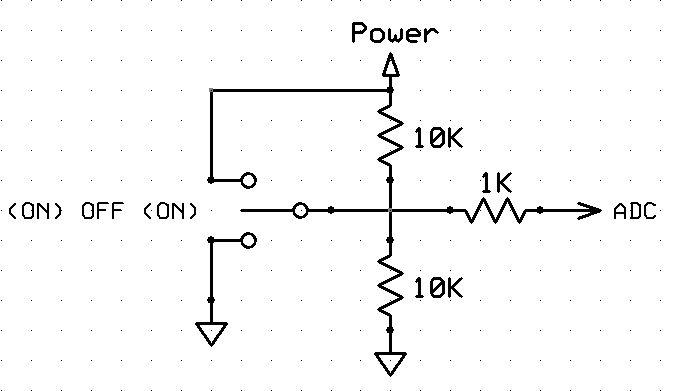
    Just make sure the switching value being monitored will not damage your uC.

    Now a simple routine can monitor and do what you need:

    Code:
    SW_1  VAR BYTE    ' A/D setup with 8bit
    
    ADCIN 0, SW_1     ' Assuming PIC Vdd is 5V and using A/D input 0
    
    SELECT CASE SW_1
       CASE IS < 26   ' Input less than 0.50V
          ' Do something
       CASE IS < 135  ' Input less than 2.64V
          ' Do something else or nothing at all
       CASE IS > 135  ' Input more than 2.64V
          ' Do something
    END SELECT
    Last edited by LinkMTech; - 20th October 2013 at 16:10. Reason: Fix schematic error
    Louie

  3. #3
    Join Date
    Jan 2010
    Posts
    88


    Did you find this post helpful? Yes | No

    Default Re: Drawing a blank on trigger pin polarity

    That initially was my thought, but my dilemma is the initial ADC supply will be 5 volts from the VR, but my input is 12 volts. I was thinking of putting a voltage divider on the input wire to supply 5 volts to the ADC pin like you show, but not sure if that would work right or what might happen when the ground signal is applied. Was thinking to maybe add a 5V Zener, but I think when the input is "floating", the ADC will find ground through the Zener.

    By the way, does ADC code run in the background like an interrupt would, or does it run in sequence like any other code? Reason being is that I am running other code on the chip right now, so that would have to be one more routine to run.

    Thanks,
    Tony

  4. #4
    Join Date
    Nov 2007
    Location
    West Covina, CA
    Posts
    219


    Did you find this post helpful? Yes | No

    Default Re: Drawing a blank on trigger pin polarity

    This schematic shows what I think you mean and might work for you.

    Name:  ADC in-2.JPG
Views: 548
Size:  33.6 KB

    The 22K is the recommended value when connected directly to RS232 voltage levels like this. The uC internal protection diodes already clamp the input signal to Vdd so the Zener is a safe option and won't start to conduct until the input approaches the rated value.


    I can't remember my voltage divider formula when it comes to introducing the 12V like this, but the results will be:
    Switch OFF : Vout = 2.5V
    Switch 12V : Vout = Somewhere between 2.5V and 5V
    Switch GND: Vout = Somewhere between 2.5V and GND

    Maybe someone can fling it mathematically or plug the values into their Proteus simulator to help me out.

    As far as the A/D module running in the background. It does, but you still have to start it with some code and I believe the only interrupt indication you get is the ADIF when the read is complete which is pretty fast anyways, in the us.
    Louie

  5. #5
    Join Date
    Jan 2010
    Posts
    88


    Did you find this post helpful? Yes | No

    Default Re: Drawing a blank on trigger pin polarity

    Got a hold of a simulator and plugged in the circuit. Actually just drew out the same circuit you had, but I had the input pin at 10K and I have a diode on the 5 V supply line to prevent any back flow if the circuit is ever turned off. With my diode in place and using the 22k resistor, I came out to:

    Switch OFF : Vout = 2.18 V
    Switch 12V : Vout = 4.01 V
    Switch GND: Vout = 1.77 V

    Thank you so much for your help.

Similar Threads

  1. Blank Variable
    By GatorGuy in forum mel PIC BASIC Pro
    Replies: 11
    Last Post: - 5th February 2010, 17:05
  2. How to reverse polarity on output pulse??
    By jellis00 in forum mel PIC BASIC Pro
    Replies: 3
    Last Post: - 6th June 2009, 13:25
  3. Error blank check
    By MINHLE in forum General
    Replies: 0
    Last Post: - 3rd December 2008, 01:56
  4. How do I detect a polarity change on an input?
    By jessey in forum mel PIC BASIC Pro
    Replies: 21
    Last Post: - 28th May 2008, 23:25
  5. max7219 blank leading zeroes
    By lutherblissett in forum General
    Replies: 0
    Last Post: - 13th November 2005, 16:46

Members who have read this thread : 1

You do not have permission to view the list of names.

Posting Permissions

  • You may not post new threads
  • You may not post replies
  • You may not post attachments
  • You may not edit your posts