Motion profile generator.


Closed Thread
Page 1 of 2 12 LastLast
Results 1 to 40 of 56
  1. #1
    Join Date
    Oct 2005
    Location
    Sweden
    Posts
    3,520

    Default Motion profile generator.

    Hi everyone,
    I'm looking for help and advice on implementing a basic motion profile generator in PBP. Ideal would be 3rd order one (linear acceleration, S-curved velocity) but the simpler 2nd order (trapezoidal acceleration, triangular velocity) proved to be hard enough to get right so I'll settle for that to begin with. Here's a crude drawing illustrating what that type of motion profile looks like:
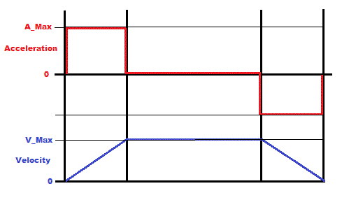
    Name:  Simple_profile.gif
Views: 3815
Size:  5.4 KB

    I'm trying to base my version on Microchips AN532, the profile generator is covered in detail in appendix E. But I'm obviously running into trouble or I wouldn't be here seeking advise.

    Without looking at any code lets just look at the theory.
    • I have a timer interrupt running, providing a system tick (the frequency doesn't matter here)
    • I have a Position variable which tells the feedback loop where the motor is supposed to be at any given time. The feedback loop plays no actual role here.
    • I have a Target variable which is to where I want the motor to move.
    • I have an acceleration value (A_Max in the above drawing), lets say this value is 10
    • I have a Velocity value which is the desired motor velocity in encoder counts per system tick at any given time.
    • I have a max velocity (V_Max in the above drawing) which is the velocity at which I want the motor to move. Lets say this value is 100

    Now lets look at how easy it is to ramp up or down the motor speed. Initially Velocity is 0:
    Each tick the value of A_Max gets added to the value Velocity. If Velocity > V_Max THEN Velocity = V_Max. The value of Velocity is added to the Position variable.
    This will ramp up the motor from 0 to V_Max and then keep it running at that velocity. Ramping it down is obviosuly equally simple, just subtract A_Max from Velocity and Velocity from Position until Velocity is 0.

    What I'm struggling with is to make it stop at the Target position.

    In the Microchip implementation they begin by dividing the total distance of the move by 2 and store that value. Then they start to accelerate the motor. Now one of two things can happen:
    1) Half the distance is covered before reaching V_Max in which case the motor is decelerated.
    2) The velocity reaches and possibly gets clamped at V_Max before half of the distance is covered.

    In (2) above they count how many ticks the velocity is at V_Max and when half the distance is covered they start subtracting from that count, one tick at the time. When the count is 0 they decelerate the motor. Pretty simple.

    If we do a move of 2000 with A_Max=10 and V_Max=100 then it would look something like this:
    Code:
    Acc	Vel	Pos	
    0	0	0	
    10	10	10	
    10	20	30	
    10	30	60	
    10	40	100	
    10	50	150	
    10	60	210	
    10	70	280	
    10	80	360	
    10	90	450	
    0	100	550	<- At V_Max (1)
    0	100	650	<- At V_Max (2)
    0	100	750	<- At V_Max (3)
    0	100	850	<- At V_Max (4)
    0	100	950	<- At V_Max (5)
    0	100	1050	<- Half distance
    0	100	1150	<- At V_Max (4)
    0	100	1250	<- At V_Max (3)
    0	100	1350	<- At V_Max (2)
    0	100	1450	<- At V_Max (1)
    0	100	1550	<- At V_Max (0)
    -10	90	1640	
    -10	80	1720	
    -10	70	1790	
    -10	60	1850	
    -10	50	1900	
    -10	40	1940	
    -10	30	1970	
    -10	20	1990	
    -10	10	2000
    Perfect! This works because everything is dividing nicely into everything else. But what happens when, for example, A_Max doesn't divide evenly into V_Max?

    Code:
    Acc	Vel	Pos	
    0	0	0	
    15	15	15	
    15	30	45	
    15	45	90	
    15	60	150	
    15	75	225	
    15	90	315	
    15	100	415	<- At V_Max (1)
    0	100	515	<- At V_Max (2)
    0	100	615	<- At V_Max (3)
    0	100	715	<- At V_Max (4)
    0	100	815	<- At V_Max (5)
    0	100	915	<- At V_Max (6)
    0	100	1015	<- Half distance
    0	100	1115	<- At V_Max (5)
    0	100	1215	<- At V_Max (4)
    0	100	1315	<- At V_Max (3)
    0	100	1415	<- At V_Max (2)
    0	100	1515	<- At V_Max (1)
    0	100	1615	<- At V_Max (0)
    -15	85	1700	
    -15	70	1770	
    -15	55	1825	
    -15	40	1865	
    -15	25	1890	
    -15	10	1900	
    -15	0	1900
    Here we end up 100 counts short of the target. I understand WHY it's happening but I can't seem to figure out a good fix for it.

    In the Microchip application note they seem to somehow determine which is resulting in the smallest error, one more or one less "tick" at V_Max. They then, obviously, opt for the one resulting in the least amount of error at the end of the profile and then they're simply "bumping" the motor to the CORRECT target position at the end of the move.

    I really can't have that - I need it to ramp down and end up exactly AT the target position.

    If anyone's got any ideas, pointers, suggestions or codesnippets I'd really appreciate the input, thanks!

    /Henrik.

  2. #2
    Join Date
    Jul 2003
    Location
    Colorado Springs
    Posts
    4,959


    Did you find this post helpful? Yes | No

    Default Re: Motion profile generator.

    I think the obvious answer is to use floating point math ...
    But then the frequency of your interrupts may become more important. How fast are they?

    Or maybe you could take the remainder of the division and add it in a separate variable on each step, and when that overflows add one to Vel.
    When ramping down, subtract 1 on an underflow instead.
    It's kind of like floating point, as long as you're just adding and subtracting 1 unit each time.
    It's harder to do than the actual floating point, but is probably faster.
    DT

  3. #3
    Join Date
    Oct 2005
    Location
    Sweden
    Posts
    3,520


    Did you find this post helpful? Yes | No

    Default Re: Motion profile generator.

    Thanks Darrel,
    The interrupt rate varies depending on application but up to 2.5kHz.

    I guess by 'the division' you mean V_Max / A_Max ? Or do you mean Distance/2 (I don't think so since the reminder will either be 0 or 1)?
    So, in the previous, non ideal example I'd get 100//15 = 10.

    From there I don't quite follow... If I keep adding 10 to a BYTE variable it'll overflow on the 26th tick which is right at the very end of the profile in that previous example, that can't be right. On the other hand, for the acceleration step:
    Code:
    Accumulator = Accumulator + Reminder
    If Accumulator >= A_Max THEN
      Accumulator = Accumulator - A_Max
      Velocity = Velocity + 1
    END IF
    Is that in line with what you're thinking?

    I need to sleep on this I think. Thanks again!

    /Henrik.

  4. #4
    Join Date
    Jul 2003
    Location
    Colorado Springs
    Posts
    4,959


    Did you find this post helpful? Yes | No

    Default Re: Motion profile generator.

    Well, I was thinking more of the decimal remainder than the modulas remainder.

    But in trying to recreate the code, I'm seeing some big limitations in the theory.
    The only way to end up at the exact Target Position, is to have a Position that is an exact multiple of V_Max.

    With V_Max = 100, you can only get target positions of 1800, 1900, 2000, 2100 etc.
    I would think you would want more precise targets ...

    Currently, I can get +/- 5 counts from those targets by using the decimal remainder idea.
    I think I can change it to reach any target position, but then I see more problems down the road.

    This only ramps from 0 to a target.
    It won't go from target to target.
    Unless there's some other steps in the process that I'm missing.

    Here's some output from the test program.
    If I can figure the rest out, I'll post the code.
    Code:
    1 = Edit Max_Acceleration (10)
    2 = Edit Max_Velocity     (100)
    3 = Edit TargetPosition   (2000)
    Enter = GO
    >
    
        0       0       0   
       10      10      10   
       10      20      30   
       10      30      60   
       10      40     100   
       10      50     150   
       10      60     210   
       10      70     280   
       10      80     360   
       10      90     450   
       10     100     550   
       10     100     650   
       10     100     750   
       10     100     850   
       10     100     950   
       10     100    1050   
       10     100    1150   
       10     100    1250   
       10     100    1350   
       10     100    1450   
       10     100    1550   
       10      90    1640   
       10      80    1720   
       10      70    1790   
       10      60    1850   
       10      50    1900   
       10      40    1940   
       10      30    1970   
       10      20    1990   
       10      10    2000   
       10       0    2000   
    
    1 = Edit Max_Acceleration (10)
    2 = Edit Max_Velocity     (100)
    3 = Edit TargetPosition   (2000)
    Enter = GO
    >1
    Enter new Max_Acceleration (10):15
    
    Max_Acceleration = 15
    
    1 = Edit Max_Acceleration (15)
    2 = Edit Max_Velocity     (100)
    3 = Edit TargetPosition   (2000)
    Enter = GO
    >
    
        0       0       0   
       14      14      14   
       14      28      42   
       14      42      84   
       14      57     141   
       14      71     212   
       14      85     297   
       14      99     396   
       14     100     496   
       14     100     596   
       14     100     696   
       14     100     796   
       14     100     896   
       14     100     996   
       14     100    1096   
       14     100    1196   
       14     100    1296   
       14     100    1396   
       14     100    1496   
       14     100    1596   
       14     100    1696   
       14      86    1782   
       14      72    1854   
       14      58    1912   
       14      43    1955   
       14      29    1984   
       14      15    1999   
       14       0    1999   
    
    1 = Edit Max_Acceleration (15)
    2 = Edit Max_Velocity     (100)
    3 = Edit TargetPosition   (2000)
    Enter = GO
    >3
    Enter new TargetPosition (2000):1800
    
    TargetPosition = 1800
    
    1 = Edit Max_Acceleration (15)
    2 = Edit Max_Velocity     (100)
    3 = Edit TargetPosition   (1800)
    Enter = GO
    >
    
        0       0       0   
       14      14      14   
       14      28      42   
       14      42      84   
       14      57     141   
       14      71     212   
       14      85     297   
       14      99     396   
       14     100     496   
       14     100     596   
       14     100     696   
       14     100     796   
       14     100     896   
       14     100     996   
       14     100    1096   
       14     100    1196   
       14     100    1296   
       14     100    1396   
       14     100    1496   
       14      86    1582   
       14      72    1654   
       14      57    1711   
       14      43    1754   
       14      29    1783   
       14      14    1797   
       14       0    1797   
    
    1 = Edit Max_Acceleration (15)
    2 = Edit Max_Velocity     (100)
    3 = Edit TargetPosition   (1800)
    Enter = GO
    >2
    Enter new Max_Velocity (100):90
    
    Max_Velocity = 90
    
    1 = Edit Max_Acceleration (15)
    2 = Edit Max_Velocity     (90)
    3 = Edit TargetPosition   (1800)
    Enter = GO
    >
    
        0       0       0   
       15      15      15   
       15      30      45   
       15      45      90   
       15      60     150   
       15      75     225   
       15      90     315   
       15      90     405   
       15      90     495   
       15      90     585   
       15      90     675   
       15      90     765   
       15      90     855   
       15      90     945   
       15      90    1035   
       15      90    1125   
       15      90    1215   
       15      90    1305   
       15      90    1395   
       15      90    1485   
       15      90    1575   
       15      75    1650   
       15      60    1710   
       15      45    1755   
       15      30    1785   
       15      15    1800   
       15       0    1800   
    
    1 = Edit Max_Acceleration (15)
    2 = Edit Max_Velocity     (90)
    3 = Edit TargetPosition   (1800)
    Enter = GO
    >
    I'm just going from your description, I haven't tried to convert the original code.

    My questions:
    • Is it supposed to be able to move to any target position? Not just a multiple of V_Max?
    • Is it supposed to move from any position to any other position?
    • Or is that part handled in your routines? And this is just a "profile" that gets mapped onto the movement?
    Last edited by Darrel Taylor; - 28th January 2013 at 05:06.
    DT

  5. #5
    Join Date
    Oct 2005
    Location
    Sweden
    Posts
    3,520


    Did you find this post helpful? Yes | No

    Default Re: Motion profile generator.

    Hi Darrel,
    Thank you very much for spending time on this, I appreciate it!
    I guess +/-5 isn't TOO bad, always ending up short of target would be better than overshooting, then I could "creep" the position the last couple of counts but obviously ending up right on the spot was/is the goal.

    Is it supposed to be able to move to any target position? Not just a multiple of V_Max?
    Yes, absolutely. Any arbitrary position.

    Is it supposed to move from any position to any other position?
    Yes, absolutely. From one arbitrary position to another, in both directions. But I guess you can think the profile generator as moving from 0 to any position by simply taking the "output-position" of the profile generator and add that to the actual position variable. Ie the profile generator creates a relative position output which is then added to the real position variable. Hope that makes sense.

    Or is that part handled in your routines? And this is just a "profile" that gets mapped onto the movement?
    Not sure I understand, or perhaps the answer to the previous question covers it (reading it again I think it did)....
    Anyway, the feedback loop moves the motor to whatever position is put in the Position variable. But I need to "move" the target position at a speed that the motor and load can follow in real life. Simply stepping the position variable +/-12345 counts (or whatever) is very hard on the motor and for the PID-loop to handle without overshooting etc. It can be handled by de-tuning the filter to less than optimal response but who wants that.

    The best way to move from one position to another is to "move" the target position at a pace that the motor can actually follow. Ie ramp it up, keep at speed, ramp it down. Or, if the move is short, ramp up and at half the distance ramp down. Ideally it should be done with a 3rd order motion profile to reduce the jerk at the beginning and end of the acceleration phase. Ie you're not only ramping up/down the velocity but your also ramping up/down the acceleration creating an S-curved velocity profile instead of one with linear "sloped". But like I said, the 2nd order one proved hard enough.

    Again, thanks!

    /Henrik.

  6. #6
    Join Date
    Jul 2003
    Location
    Colorado Springs
    Posts
    4,959


    Did you find this post helpful? Yes | No

    Default Re: Motion profile generator.

    >Thank you very much for spending time on this, I appreciate it!
    You help everyone out too, it's nice to be able to do something for you for a change.

    Thanks for the explanations, now I have a better understanding of what it needs to do.

    Although the idea of just splitting the profile in half and doing the exact same thing in reverse for the second half was interesting ... that's what's causing it to only move to multiples of V_Max. I need to change that.

    And I need to make it go both directions, it only goes forward right now.

    I hope to have something by the time you wake up in the morning.
    Sometimes being on the other side of the planet is helpful.
    DT

  7. #7
    Join Date
    Oct 2005
    Location
    Sweden
    Posts
    3,520


    Did you find this post helpful? Yes | No

    Default Re: Motion profile generator.

    Thanks Darrel!

    Actually, I don't think you should need to worry about the direction. Perhaps I misunderstood your earlier question and overcomplicated my explaination after all.

    How about this:
    * The "global position variable" is the expected motor position at any given time. The PID loop servos the motor to this position.
    * The "relative position variable" is the output of the profile generator, exactly as you shown earlier, always starting a new move at 0.
    * When a new move is commanded it is easy to calculate if the target position is positive or negative relative to the current "global position".
    * A profile, starting at 0 and ending at ABS(Target Position - Global Position) is then generated.
    * Depending on the direction or "polarity" the output of the profile generator is added or subtracted from the Global Position variable one "tick" at a time.
    * The PID loop makes the motor follow the Global Position variable very smoothly and everyone's happy, especially me :-)

    Does that make sense?

    /Henrik.

    EDIT: Put another way... Acceleration is added to Velocity. Velocity is added to RelativePosition. RelativePosition is added to OR subtracted from GlobalPosition.
    Last edited by HenrikOlsson; - 28th January 2013 at 18:08.

  8. #8


    Did you find this post helpful? Yes | No

    Default Re: Motion profile generator.

    H,
    Ditto on you always helping everyone. If this isn't too elementary relating to where your at.......

    on de-celleration when V_Max reaches to 0...zero, recalculate the ACC (will be de-celerate) val.
    if you want the same amount of iterations to de-cel as used to acelerate, at A=10 then 100/10 for 10 loops or A=15 for 100/15 for 6? or 7? loops..............
    then subtract present pos (@ V_MAX=0) from desired pos. Thats the actual steps to stopping ??
    now use sum of # loops...( sum=loops(loops+1)/2) is new ACC val to loop to 0 (zero) over that many loops (should be +- 1 or 2 from the starting ACC val)
    now there will be either 0 or some amount less than A as a final step to stop.
    should be a few more lines of code to test and calc.
    I think Darrel mentioned re-calc something.
    don
    Last edited by amgen; - 28th January 2013 at 21:06.

  9. #9
    Join Date
    Jul 2003
    Location
    Colorado Springs
    Posts
    4,959


    Did you find this post helpful? Yes | No

    Default Re: Motion profile generator.

    Maaaannnnn ... This is harder than it looks.

    Well, I have it going to the exact target position with zero error ... as long as it's able to reach the maximum velocity (the flat part of the profile).

    But if the target position isn't far enough away, and it doesn't reach V_Max before it has to decelerate ... it overshoots the center, and with the maximum deceleration (A_Max) ... the velocity can't reach 0 until it's past the target. Arrrrrggg.

    So on the shorter distances, I'll have to stop accelerating before it gets half way there, and calculate a new slope for the second half so that it stays under the maximum deceleration and gets the velocity to 0 before or at the target position. This way will make it decelerate slightly slower than it accelerates. Probably not noticable though.

    Need more time.
    DT

  10. #10
    Join Date
    Oct 2005
    Location
    Sweden
    Posts
    3,520


    Did you find this post helpful? Yes | No

    Default Re: Motion profile generator.

    Darrel,
    What, you need more time? Unacceptable, I need a working solution NOW ;-)
    Seriously, take all the time you need, I appreciate any and all help!

    I know, I found it quite a bit harder....

    Since I don't know how you're actually aproaching this I'm just thinking out loud:
    On the short moves I'm thinking how it would work out if the distance was simply cut in half and then the actual acceleration value tweaked to fit so we'd hit right on the centermark while accelerating. Then start decelerating at the same slope would make us end up at the target, right? I wonder what the worst case deviation from the set acceleration value would be... Code size and speed is obviosuly of interest as well...

    I'm looking forward to see what you come up with!

    Don,
    Perhaps Darrels aproach is exactly what you're trying to explain but I must I admit I don't quite follow what you're trying to explain.
    If an error at the end of the move of alwas less than A_Max is the best we can get then so be it but it sounds like Darrel is really onto something.

    Thank you both!
    /Henrik.

  11. #11


    Did you find this post helpful? Yes | No

    Default Re: Motion profile generator.

    Henrik,
    While the professional is working up the best scheme.

    Question..... on the last itteration to stopping, can you subtract 'position now' from 'position desired' ?
    and if so, can you move exact steps of the difference with the A value?

    Don

  12. #12
    Join Date
    Oct 2005
    Location
    Sweden
    Posts
    3,520


    Did you find this post helpful? Yes | No

    Default Re: Motion profile generator.

    Hi Don,
    If it always ends up short of the actual target AND the remaining distance TO the actual target is always less than A_Max then I could probably live with that. It means that it would always reach the actual target within a single "tick" from optimal.
    However, I'd have to move it a speed equal to the actual distance to target, if moved at A_Max then it would overshoot in one tick - which in turn gives it a little bit of "S" at the end reducing the jerk. Might actually be good.

    Thanks!
    /Henrik.

  13. #13
    Join Date
    May 2008
    Location
    Italy
    Posts
    825


    Did you find this post helpful? Yes | No

    Default Re: Motion profile generator.

    Surely I will say something obvious, but since I did not noticed it in the above post, let me say it.

    When the travel distance is less than twice the accelleration the trapezoidal profile become triangular and V max decrease, so that Vmax = tan(accelleration Slope) time the travel distance / 2

    Cheers

    Al.
    All progress began with an idea

  14. #14
    Join Date
    Jul 2003
    Location
    Colorado Springs
    Posts
    4,959


    Did you find this post helpful? Yes | No

    Default Re: Motion profile generator.

    Here's what I'm up against ...

    You can only adjust the acceleration.
    I don't see any way to know what acceleration is required to make the half-way point end up exactly at an interrupt period.
    It always ends up somewhere in the middle of a period.

    If I new what the velocity would be at the halfway point, I could adjust the acceleration so it reaches the half-way point at exactly an interrupt period.
    Except that since the acceleration changed, it won't be at that velocity at the half-way point anymore.
    So I don't see any way of predicting the half-way point in order to use the same deceleration slope it uses for acceleration (the yellow line).

    I can only change the acceleration at specific times, which coincide with the interrupt periods.
    So if I recalculate the deceleration slope at period 6 before it reaches the half-way point, it creates the green line, which should end up at the target perfectly.

    If I were to recalculate it after passing the half-way point, the deceleration rate would be higher, and violate the A_Max constraint.

    The blue line is the overshooting profile, with it's velocity using the left axis.
    The red line is the position, using the right axis.
    The parameters for that run were ... A_Max=10, V_Max=100, Target=475.


    I'm doing the green line.
    But since the green line is actually a slower velocity, it will take longer than shown in the chart to reach the target.
    But at least it is calculatable.
    DT

  15. #15
    Join Date
    Apr 2011
    Location
    Kent, UK
    Posts
    52


    Did you find this post helpful? Yes | No

    Default Re: Motion profile generator.

    It is all relative to time. One thing not concidered yet is what to do if the servo has not achieved the demand. Do you run the servo faster/slower (velocity), harder/softer rate of change (acceleration & deceleration), longer/shorter (time) or forwards/back (position) to achieve the end target?

    I assume you are attempting to modulate the velocity to achieve an end target at xx time whilst keeping the rate of change and max velocity within the set limits.

    If you concider a velocity/time graph (trapezoid shape), with velocity as the height of the perpendicular at the current time, then the distance to travel is the area under the graph from the current position. (see graph in post #1)
    The math to extract the velocity demand (in QC's / time period), at any given time, according to end target, defined limitations and servo error, is what you are trying to calculate.

    Am I helping?

  16. #16
    Join Date
    Apr 2011
    Location
    Kent, UK
    Posts
    52


    Did you find this post helpful? Yes | No

    Default Re: Motion profile generator.

    Quote Originally Posted by Darrel Taylor View Post
    You can only adjust the acceleration.
    I don't see any way to know what acceleration is required to make the half-way point end up exactly at an interrupt period.
    It always ends up somewhere in the middle of a period.
    Realistically, there will be thousands of intervals, the error will be tiny. We use an interval of 2mS and get a QC count of 1 at 15 RPM to 680 at 10,000 RPM. (using a 512 line encoded motor)
    I would suggest to leave the acceleration at the demand rate, and work out when to stop accelerating and run at a constant speed or to decelerate in time to hit the target.

  17. #17
    Join Date
    Jul 2003
    Location
    Colorado Springs
    Posts
    4,959


    Did you find this post helpful? Yes | No

    Default Re: Motion profile generator.

    Timmers,

    You are talking about the control that Henrik is using. I'm sure the intervals are much smaller, and it includes a PID loop with an encoder feedback.
    My task is to generate a "Profile" for that control to follow. A much different situation.
    DT

  18. #18
    Join Date
    Jul 2003
    Location
    Colorado Springs
    Posts
    4,959


    Did you find this post helpful? Yes | No

    Default Re: Motion profile generator.

    Henrik,

    I think i have it all working now.
    It's really ugly and needs to be cleaned up.

    But before I do that tomorrow, I have one last question.
    Would adding an "Ease From" and "Ease To" function to the beginning and end of the profile suffice for the 3rd order curve thought?
    DT

  19. #19
    Join Date
    Oct 2005
    Location
    Sweden
    Posts
    3,520


    Did you find this post helpful? Yes | No

    Default Re: Motion profile generator.

    Hi guys,

    First of all, for clarity:
    The PID-loop is already in place. It servos the motor to the position given to it and does whatever it can to bring the motor to the commanded based P,I,D and feedforward parameters. If the error between the target position and actual position gets above a setable limit the loop faults and aborts. This is one of the reasons for needing the profile generator - I can't just ask the PID-loop to move the motor 10000 QCs (quadrature counts or steps or pulses or units or whatever we want to call it) because if I do an error of an equal amount (10000) will instantly develop and the loop will fault. Even if such large errors was allowed the resulting move would be less then optimal.

    The profile generators job, being discussed here, is to generate input TO the PID-loop which the motor and load is actually capable of following.
    The input to the profile generator can then be "stepped" 10000 QCs. It then will generate a velocity profile with the parameters given to it. Each "tick" the profile generator will give the PID-loop a new position for it to move the motor to during the next time interval. The PID-loop is executed between 500 and 2500 times per second and so will the profile generator. At least that's the idea.

    Darrel,
    Although I'm having some difficulties figuring out what the worst case scenario could be with the "green line approach" I don't think doing it that way should be any problem in real life. It's better to "stretch" the deceleration phase than to violate A_Max although I would prefer it symetrical but I get what you're saying - I think.

    Thanks!
    /Henrik.

  20. #20
    Join Date
    Oct 2005
    Location
    Sweden
    Posts
    3,520


    Did you find this post helpful? Yes | No

    Default Re: Motion profile generator.

    Darrel,
    Missed your last post while composing mine.
    You mean like a initial "step" (or steps) at a velocity less than A_Max, just to "break the edge" on the trapetzoidal/triangular profile? (If not, could you clarify?)

    That could help, ideally it should be at all four "corners" of the profile but having it at the start and end of the move is certainly better than nothing.

    Thanks again Darrel!
    /Henrik.

  21. #21
    Join Date
    Jul 2003
    Location
    Colorado Springs
    Posts
    4,959


    Did you find this post helpful? Yes | No

    Default Re: Motion profile generator.

    Ok Henrik, here's what I came up with.

    To start a movement, set the three variables and call the ProfileStart subroutine.

    Code:
    MaxAcceleration = 10     ; starting values
    MaxVelocity     = 100
    TargetPosition  = 2000
    GOSUB ProfileStart
    Then for each period, call the ProfileStep subroutine, and the variables ... ThisAccel, Velocity and Position will be updated.
    When the TargetPosition has been reached, the ProfileComplete flag will be set.

    For the above values, the output of the test program looks like this ...
    Like your original example, the first column is Acceleration change, second column Velocity, third column Position.
    Code:
    1 = Edit MaxAcceleration (10)
    2 = Edit MaxVelocity     (100)
    3 = Edit TargetPosition  (2000)
    Enter = GO
    >
    
       0       0       0   
      10      10      10   
      10      20      30   
      10      30      60   
      10      40     100   
      10      50     150   
      10      60     210   
      10      70     280   
      10      80     360   
      10      90     450   
      10     100     550   
       0     100     650   
       0     100     750   
       0     100     850   
       0     100     950   
       0     100    1050   
       0     100    1150   
       0     100    1250   
       0     100    1350   
       0     100    1450   
       0     100    1550   
     -10      90    1640   
     -10      80    1720   
     -10      70    1790   
     -10      60    1850   
     -10      50    1900   
     -10      40    1940   
     -10      30    1970   
     -10      20    1990   
     -10      10    2000   
     -10       0    2000   
    
    1 = Edit MaxAcceleration (10)
    2 = Edit MaxVelocity     (100)
    3 = Edit TargetPosition  (2000)
    Enter = GO
    >
    I quickly tried the "Ease From" and "Ease To", but it messed up the final position so i pulled it back out.
    I'll have to think about it some more.

    The MaxAcceleration variable will get changed on small moves.
    So you should keep a separate variable and copy it to MaxAcceleration before starting a profile.

    Hopefully, this is somewhere close to what you were looking for.
    Try the test program, and as many combinations of the settings as you can first.
    I'd hate to ruin your CNC.

    If you can follow the code in the include file, and it makes sense ...
    You should see a psychiatrist as soon as possible.
    Attached Files Attached Files
    DT

  22. #22
    Join Date
    Apr 2011
    Location
    Kent, UK
    Posts
    52


    Did you find this post helpful? Yes | No

    Default Re: Motion profile generator.

    Henrik, I now understand what you are trying to do.

    We use our motor control for velocity regulation because we need smooth moves in our remote cameras. When we need to go to a QC position, we increment/decrement the velocity demand to achieve the target. Running it in a positional regulation tends to be quite "notchy" in our application, but I will try it and let you know how it goes.

    Tim.

  23. #23
    Join Date
    Oct 2005
    Location
    Sweden
    Posts
    3,520


    Did you find this post helpful? Yes | No

    Default Re: Motion profile generator.

    Darrel,
    Thanks a lot!
    Don't worry about ruining anything, this is for a stand alone application not related to my CNC machines. (For that you need multiple axis interpolating, all with different accelerations and velocity constraints - up for another challenge?).

    I'll take a closer look at it and run it thru its paces over the next few days. Really, thank you!

    Tim,
    Exactly, the PID-loop servos the motor to a position command. Giving it a new target position without any sort of profile doesn't work very well.
    To run at a certain velocity I make the motor "chase" an ever changing target position.

    Did you develop the code for the motion controllers you mention in PBP? Any links or information, I'd love to see them.

    /Henrik.

  24. #24
    Join Date
    Apr 2011
    Location
    Kent, UK
    Posts
    52


    Did you find this post helpful? Yes | No

    Default Re: Motion profile generator.

    Henrik,
    We work entirely in PBP. For the top end motor control and move profiling we currently use the Maxon EPOS2 controller, but we have better control at the very slow speeds than Maxon. We are moving to do all our own control including the gyro products.

    PM message sent.

  25. #25
    Join Date
    Jul 2003
    Location
    Colorado Springs
    Posts
    4,959


    Did you find this post helpful? Yes | No

    Default Re: Motion profile generator.

    Quote Originally Posted by HenrikOlsson View Post
    (For that you need multiple axis interpolating, all with different accelerations and velocity constraints - up for another challenge?).
    Sure, but it will take several months, many thousands of dollars, and a trip to Sweden.
    Let me know when you want to start.
    DT

  26. #26
    Join Date
    Oct 2005
    Location
    Sweden
    Posts
    3,520


    Did you find this post helpful? Yes | No

    Default Re: Motion profile generator.

    Hi Darrel,
    I've played around with the profile generator code and it's very cool. Unfortunately I won't pretend to understand half of it.

    There are a couple of issues, one of which I think is a bug.
    If you can, do a move with A=7, V=23, T=12345 - what do you get? When I do that it accelerates properly, runs at a velocity of 23 for a while then decides to decelerate to a velocity of 5 and finishes the move at that velocity. If I change to A=7, V=25, T=12345 it's fine but it does do similar things with other settings as well. So, I think something weird is going on there.

    The other issue is the WORD size limit on the lenght of move. I've managed to change it to LONGS (changed Position, TargetPosition, RampTotal and Value) and it seems to work that way but it is SO (I mean really) much slower to execute. What seems to be taking the longest time is the step right at the "corners" of the profile, I've seen times above 2500 cycles. I'm not sure there's anything that can be done to make it better but wanted to run it by you in case you may have some ideas.

    The last thing is one which I knew would come up from the start but I honestly couldn't imagine the code for this having to be THIS complicated and thought I'd be able to handle it outside of the actual profile generator but now I may need your input on what effects it will have on the profile generator code. The issue is resolution, or rather lack of resolution.

    Imagine a 3000rpm motor with a 500 line encoder giving 2000 counts per revolution. The servo-loop needs to run at ~1000Hz which means that lowest speed I can command is 1 count per interrupt (1000 counts per second) or 30rpm - not that great. And, even at the lowest possible acceleration of 1 count/tick/tick it'll still go from 0 to 3000rpm in 100ms.

    One possible solution might be to run the profile generator maby one in every ten servo-loop ticks. That would make it better but still pretty crude. Slower than that and it would be noticable I think.

    My original idea, which I've used before and thought I could use here as well is to use something like this:
    Code:
    Scratchpad = Scratchpad + VelocityCmd.LowByte  'Accumulate scratchpad...
    
    If ABS (ScratchPad) > 127 then              ' If it's time to move 1 count...
       Scratchpad = Scratchpad - 256           ' reset the acumulator and...
       IF Direction = FWD THEN        
           Setpoint = Setpoint + 1
       ELSE
          SetPoint = SetPoint – 1
       ENDIF
    ENDIF
        
    IF Direction = FWD THEN
       SetPoint = Setpoint + VelocityCmd.Highbyte
    Else
       SetPoint = Setpoint – VelocityCmd.HighByte
    Endif
    This allows me to set the velocity in steps of 1/256 counts per tick which is good enough and the idea was to use something similar for the acceleration. But, as I said, the profile generator code turned out to be much more complicated than I imagined and now I'm not sure I can do it without messing up the generator completely. I'm thinking I can make the velocity and acceleration variables WORD-sized and then handle the rest outside of the profile generator. What do you think, do you see any major issues with that?

    Sorry for the lengthy post and thanks again for all your help!
    /Henrik.

  27. #27
    Join Date
    Jul 2003
    Location
    Colorado Springs
    Posts
    4,959


    Did you find this post helpful? Yes | No

    Default Re: Motion profile generator.

    Yeah, I guess you could call that a bug.
    I wasn't planning on such long low speed moves.

    I can probably fix it, but it doesn't sound like this is really what you want.
    If it has to use Longs, and needs to run faster ... the time it takes my approach to process each step will never meet your requirements.

    Maybe a different approach is in order.
    But I don't know what that would be.

    Sorry.
    DT

  28. #28
    Join Date
    Oct 2005
    Location
    Sweden
    Posts
    3,520


    Did you find this post helpful? Yes | No

    Default Re: Motion profile generator.

    Hi Darrel,
    Now I feel really bad.
    It's not that it doesn't do what I want. It does exactly what I want just not under all conditions. Conditions which are a given for me but definitely not for you and now you've wasted a lot of time on something just because I didn't manage to explain the application in enough detail. I'm the one who should say I'm sorry.

    I keep finding articles and application notes on acceleration profiles and positioning but they all seam to targeting step motor application where you obviously move the motor only one step per "tick" so you can easily "hit" the exact centerpoint and deceleration point of the move. Not so here....

    I will keep dwelling on this and trying a couple of things. I keep thinking that perhaps I could live with the acceleration constraint being violated (to some extent) on deceleration, what I can not accept is not overshooting the target.

    Thanks!
    /Henrik.

  29. #29
    Join Date
    May 2013
    Location
    australia
    Posts
    2,386


    Did you find this post helpful? Yes | No

    Default Re: Motion profile generator.

    henrik
    did you ever get this working ?
    I have been messing with this for years and think I have finally worked it out . my solution is in C code but the idea is probably fairly portable if your interested

  30. #30
    Join Date
    Oct 2005
    Location
    Sweden
    Posts
    3,520


    Did you find this post helpful? Yes | No

    Default Re: Motion profile generator.

    Hi Richard,
    I have been working on it on and off but have yet to actually try it on real hardware. It's been over 6 months since I last looked at the code but the way I left it was that it figured out when it needed to start decelerating (which could be up to VMax past the ideal position) and then recalculating the needed deceleration value each tick untill ending up at the target. Basically this aproach WILL cause the decleration to be "steeper" than the acceleration which I know I said I don't want but in reallity I don't Think it'll matter that much, I mean, in simulation where a "move" is 100 "ticks" in total it looks "brutal" but in reallity I don't Think it'll be that bad.

    I have NO idea why you write in C (just kidding) but I'd love to see your code, thanks for offering!

    /Henrik.

  31. #31
    Join Date
    May 2013
    Location
    australia
    Posts
    2,386


    Did you find this post helpful? Yes | No

    Default Re: Motion profile generator.

    my basic premise is that the input to the pid filter is velocity error (not position error) . the required velocity (setpoint) is found from a lookup tables who's in put is based on position . The move routine has 5 possible modes 4 is start a new move , 3 accelerate ,2 steady speed (cruise) ,1 decelerate, 0 in position , -1 stalled (failure).
    The lookup table was developed by - getting motor running at various velocities and throwing the brakes on (l393d style) and measuring the number of ticks travelled till at rest ,
    I plotted these in a spread sheet (the motor I'm using is a 171:1 gear motor 564 ticks per rev, target vel is 32 rpm ) interestingly the pos vs vel curve is ver nearly parabolic.
    the clever bit is using two lookup tables "the multi_map function" to interpolate the best velocity for the current position using only 9 entries in each table
    Attached Files Attached Files

  32. #32
    Join Date
    May 2013
    Location
    australia
    Posts
    2,386


    Did you find this post helpful? Yes | No

    Default Re: Motion profile generator.

    some debug runs
    Attached Files Attached Files

  33. #33
    Join Date
    May 2013
    Location
    australia
    Posts
    2,386


    Did you find this post helpful? Yes | No

    Default Re: Motion profile generator.

    beginning to think this may never fly in pbp
    I can get various versions to work in C using integer math , but with a real servo motor with 2000 counts /rev the numbers get out of control.
    although it seems to be workable using a 16f1825 @32mhz using C with floats.
    however using toy servos like the polou gearmotors at modest speeds and a nice faulhaber (probably not a toy ) I found on ebay its probably doable in pbp certainly works with C integer math even limited to 16 bit vars
    the pid refresh rate is critical nothing less than 10ms will work for real servos, up to 100ms can work for the others
    I have attached a xlsm spread sheet to show lookup table ideas
    Attached Files Attached Files
    Last edited by richard; - 6th September 2014 at 08:44. Reason: convert to english

  34. #34
    Join Date
    May 2013
    Location
    australia
    Posts
    2,386


    Did you find this post helpful? Yes | No

    Default Re: Motion profile generator.

    funny I have been wondering why I can get this stuff to work on a atmega328 @16mkz clk without too much trouble , but with a pic18f45k40 @64mhz clk the performance is patchy
    then I found this link
    http://www.t4f.org/articles/optimiza...-and-pro-mode/
    i'm staggered it's as if microchip don't want hobbyists to use their products
    what amateur wants to pay $995 us for a complier ,why even have a free option that's so badly compromised
    I'm considering changing camp to atmel

  35. #35
    Join Date
    May 2013
    Location
    australia
    Posts
    2,386


    Did you find this post helpful? Yes | No

    Default Re: Motion profile generator.

    henrik

    best I have come up with is assuming your time intervals are constant :-
    distance is the lessor of (normal full accel ramp ) or travel /2
    max velocity is the lessor of sqr( 2*accel*distance/2) or vmax

    next position = (current velocity + accel/2)+current position .
    while pos+next position<= dist/2 . from then on either constant v or decelerate mode
    I'm assuming pid routine can limit vel to vmax

    question here is what to do with the error and what is the error is it failure to reach next position or failure to achieve target velocity ?.

    it must fit into a lookup table somehow that way you could compensate for errors

    still thinking

  36. #36
    Join Date
    Oct 2005
    Location
    Sweden
    Posts
    3,520


    Did you find this post helpful? Yes | No

    Default Re: Motion profile generator.

    Hi Richard,
    Sorry for the late reply, been a bit busy here.
    I thought about commenting on the issue with C compilers and the whole AVR vs PIC etc but I don't write code in C and I don't use AVRs so I simply won't.

    I don't think the aproach with a lookup table for velocity is the way to go in my particular case. I can see it working in a specific application where you can tweak its value etc but what I want is a general purpose routine. I'm just starting to get back into this, setting up a small testbed with a little servo motor, 500 line encoder and LMD18200 H-bridge driver chip.

    My aproach, as it currently stands is based on around a basic state machine with four states - Stopped, accelerating, traversing, decelerating. Timing is very consistent, being interrupt driven, calls to the PID routine is currently at 1000-2500Hz (user selectable) but I think I need to allow a divisor between it and the profile generator.Basically, here's how it works:

    I've got:
    [Desired velocity] <- Set by user
    [Desired position] <- Set by user
    [Desired acceleration] <- Set by user

    [Output velocity]
    [Output position]
    [Output acceleration]

    On the very first call to the state machine when a new move is about to begin variables are initialized and [Desired position] is recalculated into a relative distance from the current position of the motor.

    In the acceleration state [Output velocity] is increased by [Desired acceleration]. Then [Output position] is increased or decreased by [Output velocity].
    If [Output velocity] is equal to or larger than [Desired velocity] it's clamped (before manipulating [Output position] ), the traveled distance is stored and the state is changed to traversing.
    If [Output position] is equal to or larger than [Desired position] / 2 the state is changed to decelerate.

    In the traversing state [Output position] is increased or decreased by the set velocity. If the output position is equal to or less than [Desired position] - "distance traveled during acceleration" state is changed to decelerate.

    In the deceleration state the [Output acceleration] is recalculated each tick based on [Output acceleration] = [Output velocity] ^ 2 / 2d where d is the distance left to target. [Output acceleration] is subtracted from [Output velocity] which is added to or subtracted from [Output position].

    Now, this will, most of the time, violate [Desired acceleration] when decelerating which I initially said was unacceptable. However, given the fact that the motor position is commanded and sampled at discrete time intervals and is allowed to move an arbitrary amount of counts (any velocity) I simple can't see a way to make it accelerate/decelerate with set rate, run at speed and end up at exactly the desired position - all at once. It's not perfect but just like timmers said early on the deceleration will likely be stretched out over hundreds or even thousands of ticks so in real life it might not even be noticable.

    Now I just need to get that little testbed up and running....

    /Henrik.

  37. #37
    Join Date
    May 2013
    Location
    australia
    Posts
    2,386


    Did you find this post helpful? Yes | No

    Default Re: Motion profile generator.

    I have noticed another problem with my methods ,in that I'm calculating velocity by subtracting pos from old postion in the pid loop. when under acceleration this is actually average velocity not the actual (final)
    velocity . I have not been successful in determining velocity without impinging on pid evaluation time.
    using floating point routines with a 8bit cpu the highest pid rate I can achieve is 250 hz so average velocity is not good enough. might mean fp pid is not worth pursuing
    general purpose might be a tall order . I have a leadshine dcs303 digital dc servo driver , it runs a dcm50202 servo motor / 500line en with no problems (can achieve 3000 rpm and move to pos +- 1 count) . It will not even come close to achieving servo lock on the other motors I'm using. my other motors have a really high inertia this makes them more predictable for my "slow" routines providing you don't try to exceed their accel profiles. the low inertia servo is problematic

  38. #38
    Join Date
    Nov 2003
    Location
    Greece
    Posts
    3,802


    Did you find this post helpful? Yes | No

    Default Re: Motion profile generator.

    I am not an expert on this subject but would try to help. Is it necessary to use the PID routine all the time?

    Why not just call it just before the target point is close so that it will be used less and everything will be running much faster?

    Maybe I am away from what is discussed here... Just a thought.

    Ioannis

  39. #39
    Join Date
    Oct 2005
    Location
    Sweden
    Posts
    3,520


    Did you find this post helpful? Yes | No

    Default Re: Motion profile generator.

    Richard,
    Yes, I think floating point is going to take too much resources and I'm not sure it'll actually solve anything. The position is still "set" and sampled at discrete intervals, there's no way to force it to "hit" a specific position at a discrete interval while still allowing "any" velocity and "any" acceleration. If target position is NOT to be violated then something else will have to give. Either change velocity so deceleration can start at exactly the correct spot. Or change deceleration so the position will end up at the correct spot once velocity reaches zero. I'm opting for the second....

    I have successfully used my PID code with step and direction input running a motor with a 3600 line encoder at 4000rpm (960kHz step frequency), it'll position to 1 count without problem. The PID is executed at 1500Hz with processing power to spare. Here it is: ,

    for more details see my webpage. But it's being commanded by an external motion control software which is what generates the motion profile. The DCS303 manual mentions built in motion controller for self thest with trapezoidal velocity profile which is exactly what I'm trying to achieve. Unfortunately the DCS303 manual doesn't say much about how its profile generator works and/or which set parameters it may "violate" (if any) to achieve its goal.

    Ioannis,
    YMMV of course but in my case I'd say yes, it's neccesary. It's not just a matter of moving from point A to B as fast as possible, I want the motor to move from point A to point B following the profile generated by the code discussed here as closely as possible. Without the closed loop in there the motor could potentionally stall in the middle of the move.

    Fun stuff this....

    /Henrik.

  40. #40
    Join Date
    May 2013
    Location
    australia
    Posts
    2,386


    Did you find this post helpful? Yes | No

    Default Re: Motion profile generator.

    henrik
    will this profile generator acutally "control" the motor or just output pulses/dir to another step /dir controller ?
    I'm thinking in the later case you have would heaps of time to do the sums and design a profile and then just output the pulses when prepared.
    to accelerate just decrement/increment the pulse interval by a fixed amount , the first and last few pulses and maybe even the transition to constant velocity could all be given special treatment. that treatment would need to be customised for motor/load/inertia as would max velocity and acceleration. bit like mach3 in a pic ?

Similar Threads

  1. Motion Capturing
    By koossa in forum Off Topic
    Replies: 0
    Last Post: - 30th June 2009, 11:05
  2. Suggest a motion sensor Please
    By sougata in forum mel PIC BASIC Pro
    Replies: 4
    Last Post: - 4th March 2007, 13:22
  3. Wireless Motion Sensors.
    By koossa in forum mel PIC BASIC Pro
    Replies: 9
    Last Post: - 17th October 2006, 21:57
  4. Need low Profile LCDs
    By Foxx373 in forum General
    Replies: 8
    Last Post: - 26th October 2005, 17:33
  5. Motion Tracking
    By JEC in forum mel PIC BASIC Pro
    Replies: 5
    Last Post: - 5th November 2004, 00:58

Members who have read this thread : 2

You do not have permission to view the list of names.

Posting Permissions

  • You may not post new threads
  • You may not post replies
  • You may not post attachments
  • You may not edit your posts