Greeting...I am trying to Connect two PIC microcontrollers


Closed Thread
Results 1 to 8 of 8
  1. #1
    Join Date
    Nov 2012
    Posts
    4

    Default Greeting...I am trying to Connect two PIC microcontrollers

    Hi Everyone,

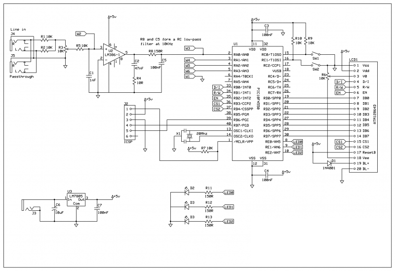
    I join here looking for ideas and help on a project that I am trying to build. What I want to have the main system which I am showing here with the schematic. I want to have a 3x4 keypad for the user to input values. What I came across is that all the pins on that schematic are being used. So the question of using two pics came across, one as a slave and one as a master. But I have no idea how the wiring/ connection are going to be. Once I figure that out I will look into the coding next.

    This is the 3x4 device, http://www.pcreview.co.uk/forums/3x4...-t3043773.html
    I am using a PIC18F4550, http://ww1.microchip.com/downloads/e...doc/39632c.pdfName:  800px-Real-time_Spectrum_Analyser.png
Views: 4437
Size:  173.7 KB

  2. #2
    Join Date
    Oct 2005
    Location
    Sweden
    Posts
    3,519

    Default Re: Greeting...I am trying to Connect two PIC microcontrollers

    Hi,
    What do you mean by all pins are being used?
    A 4x3 matrix would require 7 pins and I see 8 free pins (RC2-7, RA4-5, RB5) on the '4550 in your schematic...

    If you put a slave PIC on the keypad you could program it to SEROUT/HSEROUT a byte each time a key is pressed and connect it to the USART of the 4550 (RC7 is the RX input for the USART and is currently not used in your schematic.)

    /Henrik.

  3. #3
    Join Date
    Nov 2012
    Posts
    4

    Default Re: Greeting...I am trying to Connect two PIC microcontrollers

    Hi,
    Thank you for your response and I am glad I found your answer. You are right there is more pins that the 3x4 can use. If you will, please guide me with the wiring connection. How would you connect the 3x4 keypad to the PIC18f4550? What pins from the keypad to what pins from the PIC?

    Thank you for your time.

  4. #4
    Join Date
    Oct 2005
    Location
    Sweden
    Posts
    3,519

    Default Re: Greeting...I am trying to Connect two PIC microcontrollers

    Hi,
    For a basic 4x3 matrix you need 4 output and 3 inputs OR 3 outputs and 4 inputs - up to you really. The outputs drives the columns (or rows) and the inputs reads the rows (or columns).
    Pull up the inputs, drive one of the outputs low, read the inputs. If any of the inputs reads low you have a button pressed. Drive the next input low, read the inputs and so on.

    If you search the forum I'm sure you'll find examples.

    /Henrik.

  5. #5
    Join Date
    Nov 2012
    Posts
    4

    Default Re: Greeting...I am trying to Connect two PIC microcontrollers

    In my situation, I have different pins left. I attached the schematic of one of the forums keypad. Please help me choose the pins for the schematic I am working on, by comparing it to the attached image. Thank you, I am grateful.
    Name:  keypad.jpg
Views: 4118
Size:  207.7 KB
    Last edited by Freestyle; - 19th November 2012 at 21:42.

  6. #6
    Join Date
    Oct 2005
    Location
    Sweden
    Posts
    3,519

    Default Re: Greeting...I am trying to Connect two PIC microcontrollers

    Hi,
    I really don't understand. Use any four of the available pins as outputs and any three of the available pins as inputs - or the other way around - that's it.

  7. #7
    Join Date
    Nov 2012
    Posts
    4

    Default Re: Greeting...I am trying to Connect two PIC microcontrollers

    Thank you,

    I am embarrassed to ask this.. I found this website but not sure what pins are what in the actual keypad. May you help me with it?
    http://www.pic-tronics.com/7-Segment...eypad-Int-.php

    this is the schematic http://www.acroname.com/robotics/par...3X4-KEYPAD.pdf

  8. #8
    Join Date
    Oct 2005
    Location
    Sweden
    Posts
    3,519

    Default Re: Greeting...I am trying to Connect two PIC microcontrollers

    Hi,
    Look at the table on the datasheet. It'll tell you that when '1' is pressed you'll get a connection between pins 2 and 3. When '2' is pressed you'll get a connection between pins 2 and 1 and when '3' is pressed you'll get a connection between pins 2 and 5.
    This means that since '1' and '2' and '3' are on the same row the common connection to that row must be pin 2. The connection to column 1 would be pin 3, column 2 would be pin 1 and column 3 would be pin 5.

    If you draw that out on paper you'll get something looking like this:

    Name:  Keypad.JPG
Views: 5010
Size:  74.0 KB

    Hope it helps.

    /Henrik.

Similar Threads

  1. Single PIC to Blink 5 LEDs Independently?
    By RossWaddell in forum mel PIC BASIC Pro
    Replies: 68
    Last Post: - 18th July 2015, 16:56
  2. Which pic? up to date basic chip for 16f877
    By tasmod in forum mel PIC BASIC Pro
    Replies: 12
    Last Post: - 19th November 2012, 11:26
  3. How not to prototype your next PIC project
    By SteveB in forum General
    Replies: 3
    Last Post: - 12th November 2012, 09:35
  4. Programming for Microcontrollers in C
    By erice1984 in forum Off Topic
    Replies: 1
    Last Post: - 1st May 2009, 17:12
  5. Play Music (MP3, WAV,...) for greeting card
    By flotulopex in forum mel PIC BASIC Pro
    Replies: 9
    Last Post: - 10th January 2007, 15:14

Members who have read this thread : 1

You do not have permission to view the list of names.

Posting Permissions

  • You may not post new threads
  • You may not post replies
  • You may not post attachments
  • You may not edit your posts