DT_Analog & 12F1822 internal voltage reference


Closed Thread
Results 1 to 19 of 19
  1. #1

    Default DT_Analog & 12F1822 internal voltage reference

    Can I use the DT_Analog routine to read the internal 1.024 voltage reference in the 12F1822 chips?

    I'm using the system in my BMS to measure the chip supply voltage and it has worked for years using an external voltage ref LM385 on one of the adc pins and a 12F683.

    This is just a natural progression to reduce the component count and increase accuracy.

    Any issues look likely?

  2. #2
    Join Date
    May 2004
    Location
    NW France
    Posts
    3,614


    Did you find this post helpful? Yes | No

    Default Re: DT_Analog & 12F1822 internal voltage reference

    Hi,

    USING the internal reference is more than possible ... but READING it looks a bit strange

    Why would you use Darrel's routine for such a job ???

    Have a look to my last post http://www.picbasic.co.uk/forum/show...020#post117020 ... it' purpose is to read the supply voltage of the chip !!!

    Alain
    ************************************************** ***********************
    Why insist on using 32 Bits when you're not even able to deal with the first 8 ones ??? ehhhhhh ...
    ************************************************** ***********************
    IF there is the word "Problem" in your question ...
    certainly the answer is " RTFM " or " RTFDataSheet " !!!
    *****************************************

  3. #3
    Join Date
    Jul 2003
    Location
    Colorado Springs
    Posts
    4,959


    Did you find this post helpful? Yes | No

    Default Re: DT_Analog & 12F1822 internal voltage reference

    Quote Originally Posted by retepsnikrep View Post
    Can I use the DT_Analog routine to read the internal 1.024 voltage reference in the 12F1822 chips?
    Of course you can.

    This is just a natural progression to reduce the component count and increase accuracy.
    Well, ... it will reduce the component count. It doesn't use any pins. And it will increase the resolution.
    But it won't necessarily increase the "Accuracy".

    When they say a "Fixed 1.024V reference" it sounds really good.
    Untill you look at the specs. +6/-8%, and -114 PPM/°C

    6% of 1.024V = 0.06144V
    8% of 1.024V = 0.08192V

    So that 1.024V can be any where between 0.94208 and 1.08544V, when it's at 25°C.
    Add in some wide temperature fluctuations, and it doesn't look much like a "Reference" anymore.

    The 1822 also has an on-chip temperature sensor, so some of those variations can be removed, but the "accuracy" is still off without calibration.
    If calibrated, you can get some amazing results using DT_Analog, but every chip must be calibrated individually.

    Disregarding the tolerances, here's a routine that will read VDD on a 12F1822 (without DT_Analog).
    I'm assuming it's a battery operated device, and only have the FVR turned on while reading it to save current.
    Code:
    DEFINE ADC_BITS 10
    ADvalue  VAR WORD
    VDD      VAR WORD
    
    
    ;----[Get VDD by reading the FVR]-----------------------------------------------
    VDD_Res  CON 10              ; A/D resolution (bits) used for VDD measurement
    FVrefMV  CON 1024            ; Fixed Vref Voltage in mV  ( must match FVRCON )
    Vref_AD5 CON EXT             ; Calculate FVref A/D reading when VDD = 5.00V
    @Vref_AD5 = (_FVrefMV*100000) / (500000000/(1023 << (_VDD_Res-10)))
    
    GetVDD:
        ADCON1 = %10110000       ; A/D Right Justified, FRC clock
        FVRCON = %10000001       ; Enable Fixed Voltage Reference (1.024V)
        WHILE !FVRCON.6 : WEND   ; Wait for fixed ref to be stable
        ADCIN 31, ADvalue        ; Read the FVR channel
        FVRCON = 0               ; Disable Fixed Voltage Reference
        VDD = Vref_AD5           ; calculated Vref A/D at 5.00V
        VDD = VDD * 500          ;   * 500  - two decimal places
        VDD = DIV32 ADvalue      ;   / FVRef reading - converts to VDD volts
    RETURN
    Just GOSUB GetVDD and the result is returned in the VDD variable with two decimal places (5.00V = 500).
    That is actually good enough for most battery powered applications that need to react to the VDD voltage.
    It doesn't use the extra current required for a voltage divider, and doesn't use a pin to read it.
    A voltage divider would draw current all the time, even when the PIC is asleep. This won't.

    Similarly, here's a routine that does use DT_Analog to get 16-bit readings from the reference.
    Code:
    INCLUDE "DT_Analog.pbp"      ; DT's 16-bit Analog Module
    DEFINE ADC_BITS 10
    VDD      VAR WORD
    
    
    ;----[Get VDD by reading the FVR]-----------------------------------------------
    VDD_Res  CON 16              ; A/D resolution (bits) used for VDD measurement
    FVrefMV  CON 1024            ; Fixed Vref Voltage in mV  ( must match FVRCON )
    Vref_AD5 CON EXT             ; Calculate FVref A/D reading when VDD = 5.00V
    @Vref_AD5 = (_FVrefMV*100000) / (500000000/(1023 << (_VDD_Res-10)))
    
    GetVDD:
        ADCON1 = %10110000       ; A/D Right Justified, FRC clock
        FVRCON = %10000001       ; Enable Fixed Voltage Reference (1.024V)
        WHILE !FVRCON.6 : WEND   ; Wait for fixed ref to be stable
        ADchan = 31              ; FVR channel
        ADbits = VDD_Res         ; set the results resolution
        GOSUB GetADC             ; Get A/D value
        FVRCON = 0               ; Disable Fixed Voltage Reference
        VDD = Vref_AD5           ; calculated Vref A/D at 5.00V
        VDD = VDD * 500          ;   * 500  - two decimal places
        VDD = DIV32 ADvalue      ;   / FVRef reading - converts to VDD volts
    RETURN
    That version gives much more resolution, but only a small amount of accuracy, and only because the steps are smaller.
    However, it gives the possibility of VERY accurate readings, if the FVR voltage is calibrated.

    If you can determine the actual FVR voltage, the FVrefMV constant can be changed to match, which makes for incredibly accurate readings. (At room temperature).
    For now, lets assume you won't need the calibration. Why ... because it's midnight here.
    Last edited by Darrel Taylor; - 6th November 2012 at 18:31. Reason: spelling and Vref_AD5 calc.
    DT

  4. #4


    Did you find this post helpful? Yes | No

    Default Re: DT_Analog & 12F1822 internal voltage reference

    Thanks for that excellent reply.

    OK lets talk about calibrating it for the extra accuracy. ?

  5. #5
    Join Date
    May 2006
    Location
    Del Rio, TX, USA
    Posts
    343


    Did you find this post helpful? Yes | No

    Default Re: DT_Analog & 12F1822 internal voltage reference

    To make this more portable could we do the following?
    Code:
    DEFINE ADC_BITS 10
    ADvalue  VAR WORD
    VDD      VAR WORD
    
    
    ;----[Get VDD by reading the FVR]-----------------------------------------------
    VDD_Nom	 CON 500	     ; Nominal Value of VDD*100. 500 for 5V, 300 for 3V
    VDD_Res  CON 10              ; A/D resolution (bits) used for VDD measurement
    FVrefMV  CON 1024            ; Fixed Vref Voltage in mV  ( must match FVRCON )
    Vref_AD5 CON EXT             ; Calculate FVref A/D reading when VDD = VDD_Nom
    @Vref_AD5 = (_FVrefMV*100000) / (VDD_Nom*1000000/(1023 << (_VDD_Res-10)))
    
    GetVDD:
        ADCON1 = %10110000       ; A/D Right Justified, FRC clock
        FVRCON = %10000001       ; Enable Fixed Voltage Reference (1.024V)
        WHILE !FVRCON.6 : WEND   ; Wait for fixed ref to be stable
        ADCIN 31, ADvalue        ; Read the FVR channel
        FVRCON = 0               ; Disable Fixed Voltage Reference
        VDD = Vref_AD5           ; calculated Vref A/D at VDD_Nom
        VDD = VDD * VDD_Nom      ; * Vdd_nom gives two decimal places
        VDD = DIV32 ADvalue      ;   / FVRef reading - converts to VDD volts
    RETURN

  6. #6
    Join Date
    Jul 2003
    Location
    Colorado Springs
    Posts
    4,959


    Did you find this post helpful? Yes | No

    Default Re: DT_Analog & 12F1822 internal voltage reference

    That's great Steve!
    You actually saw how it works.

    And as a "Single Point" calibration, it should definitely be calibrated as close to the "nominal" voltage as possible.
    However, there's an interesting twist to the calibration procedure, which I'll try to cover first...

    Quote Originally Posted by retepsnikrep
    OK lets talk about calibrating it for the extra accuracy. ?
    OK, let's ...

    Remember that Calibration can only be as accurate as the Test Equipment used to calibrate it.
    Using a handheld voltmeter with it's Low Battery indicator flashing ... probably isn't the best tool.
    I rely on a Tektronix Digital scope for my readings, but it has never been calibrated so I'm sure it's not perfect. (There's really no such thing as "Perfect").

    Manual calibration of the FVR is fairly simple. All you need is ...
    1. The current VDD voltage during the test.
    2. The A/D reading of the FVR at that voltage.
    3. The Maximun Possible A/D value. (65472 for 16-bit DT_Analog)
    For example, on a 12F1822 here I read ...

    VDD = 5.11 V <-- Measured VDD voltage
    ADC = 13307 <-- Actual A/D reading from the FVR

    So you can use a calculator, spreadsheet or your superior mental abilities to do ...

    V = VDD / MAXad * ADC
    V = 5.11 / 65472 * 13307
    V = 1.039

    Adjust the constant to match the measured FVR voltage ...
    Code:
    FVrefMV  CON 1039            ; Fixed Vref Voltage in mV  ( must match FVRCON )
    And you have a nice single point calibration that will read exactly the same voltage as the test equipment at the test conditions.

    So here's the "twist".
    Since the calibration formula includes the measured VDD, the math doesn't care if it's 3V or 5V.
    The end result is the voltage of the internal reference.

    If the test VDD was 3V, and the A/D reading was 22675 ...

    V = VDD / MAXad * ADC
    V = 3.00/ 65472 * 22675
    V = 1.039

    So the FVrefMV CON 1039 is the same either way, and it's the only thing that gets changed in the program.
    The math in the program uses 5V as a key datapoint, but the actual calibration voltage doesn't have to be that.

    But the truth is ... if you calibrated it at 3.00V, the A/D result would NOT be 22675.
    The so called "Fixed" voltage reference, varies with VDD.
    So for accuracy across the full range, you need at least a two point calibration.

    How do you do a "Two Point" calibration of the Fixed Voltage Reference?
    I don't know, I haven't done it yet.

    Get me started ... I dare ya

    .
    Last edited by Darrel Taylor; - 7th November 2012 at 05:53.
    DT

  7. #7


    Did you find this post helpful? Yes | No

    Default Re: DT_Analog & 12F1822 internal voltage reference

    Thanks for even more great ideas.

    Maths is not my strong suit but i am getting a handle on how it works.
    I worked for years using an external reference and a 12F683 calculating it's own VDD for my BMS.

    What is confusing me is why we have an EXT variable and then this huge formula in assembly. Why?
    Preumably because it can't fit into 16 bit integer maths even with DIV32
    In assembler on the 12F1822 do we have 32 bit maths?

    Code:
    Vref_AD5 CON EXT             ; Calculate FVref A/D reading when VDD = VDD_Nom
    @Vref_AD5 = (_FVrefMV*100000) / (VDD_Nom*1000000/(1023 << (_VDD_Res-10)))
    I appreciate the accuracy will vary over the VDD range i'm more interested in how it changes with temperature for now.

    I suppose I could calculate the vref for each chip at various temps from 0-40C at 5C intervals then use a lookup table to pick the right one to use based on the chips own internal temp reading taken just prior to reading the VDD.

    All good stuff. I'm going to be doing some bench testing very shortly to see how it works in practise.

    I'm very disapointed you won't let me use my $5 multimeter with dying battery to calibrate my whole system

    If you had a very accurate calibrated computer controlled psu you could do calibration at any voltage you wanted. But as you say the VDD is already in the maths so why not just calibrate at a nominal 5v and at 3V using a lithium button cell or something as the supply. Then work out the relationship or slope changes between them both.

    In practical terms my program might need to do a few things.

    1) Have a 3.3v calculated constant vref in eprom. (I'll probably use 3.3v based constant as that's where the cells spend most of the time)
    2) Get it's own temp prior to measuring it's own VDD and compensate according to prev temp variation data points.
    3) Measure it's own VDD using the 3.3V constant. V = 1.039 or whatever
    4) Use the measured VDD to load a new constant value if reqd due to change in VDD. Say cell is at 3.65V in this example
    5) Finally use the new constant to read it's own vref again to have a final value VDD

    I will be happy with ACTUAL in use accuracy to within +/- 25mv as that's about what I manage at present.

  8. #8
    Join Date
    May 2006
    Location
    Del Rio, TX, USA
    Posts
    343


    Did you find this post helpful? Yes | No

    Default Re: DT_Analog & 12F1822 internal voltage reference

    Quote Originally Posted by Darrel Taylor View Post
    You actually saw how it works.
    I'll confess, it was a head scratcher. After a few reads, an excel spreadsheet to see some numbers, and digging into the data sheet to confirm FVR could be read by the ADC while the ADC Vref was set to 'something' else, the light bulb came on.

  9. #9
    Join Date
    May 2006
    Location
    Del Rio, TX, USA
    Posts
    343


    Did you find this post helpful? Yes | No

    Default Re: DT_Analog & 12F1822 internal voltage reference

    Quote Originally Posted by retepsnikrep View Post
    What is confusing me is why we have an EXT variable and then this huge formula in assembly. Why?
    Preumably because it can't fit into 16 bit integer maths even with DIV32
    In assembler on the 12F1822 do we have 32 bit maths?

    Code:
    Vref_AD5 CON EXT             ; Calculate FVref A/D reading when VDD = VDD_Nom
    @Vref_AD5 = (_FVrefMV*100000) / (VDD_Nom*1000000/(1023 << (_VDD_Res-10)))
    That formula is composed entirely of constants, and is assigned to a constant. So, it is evaluated at compile time (by your 64 bit computer) and the integer value is assigned to the the constant "Vref_AD5". For 5v it ends up being 209.

  10. #10
    Join Date
    Oct 2009
    Location
    Utah, USA
    Posts
    427


    Did you find this post helpful? Yes | No

    Default Re: DT_Analog & 12F1822 internal voltage reference

    My code below (using Darrels example to read VDD) is only displaying 65535 on my LCD???

    This is on my breadboard with the PICkit2 supplying the 5vdc (4.87 measured w/voltmeter)

    Any suggestions on why I am not seeing 4.87??


    Code:
            '       Pic Configuration
            '       =================
    #CONFIG
       __CONFIG _CONFIG1, _FCMEN_OFF & _IESO_OFF & _BOREN_OFF & _FOSC_INTOSC & _WDTE_OFF & _MCLRE_OFF & _PWRTE_OFF
       __CONFIG _CONFIG2, _LVP_OFF
    #ENDCONFIG


    ' -----[ Initialization ]--------------------------------------------------
    Reset:
    
    
            DEFINE OSC 4
            OSCCON    = %01101010
            TRISA     =   %001010                ' PortA.3 is button input, A.1 is a/d in
            ANSELA    =     %0010                ' Turn on Analog for AN1 (PortA.1)
            PORTA     = 0                        ' all outputs zero
            CM1CON0.7 = 0                        ' Disable comparator                   
            CCP1CON   = %00001100                ' CCP in PWM mode
            APFCON    = %00000001                ' Move PWM to PortA.5
    ADCON0    = %00000111   'x,AN1,AD enabled
    
    define adc_bits 10            'set up the a/d converter
    define adc_clock 3
    define adc_sampleus 50


            '   
            '       Software variables
            '       ==================
        Duty    VAR WORD
        stepp   var byte
        Cmd     CON $FE        'LCD prefix for Command
        Clr     con 1          'LCD CLEAR SCREEN
        Hm      con 2          'LCD HOME COMMAND
        ADvalue var word
        VDD     var word
    
    VDD_Res  CON 10              ; A/D resolution (bits) used for VDD measurement
    FVrefMV  CON 1024            ; Fixed Vref Voltage in mV  ( must match FVRCON )
    Vref_AD5 CON EXT             ; Calculate FVref A/D reading when VDD = 5.00V
    
    @Vref_AD5 = (_FVrefMV*100000) / (500000000/(1023 << (_VDD_Res-10)))
        
            ' ----------------[ I/O Definitions ]-----------------------------------
            LED     var PortA.0              ' LED indicator
            Chg     VAR PORTA.2              ' FET to control charge current
            Btn     var PORTA.3              ' push button input
            Light   con 1                    ' Constant for HPWM channel 1 PortA.5
    
    
    ' -----[ Program Code ]----------------------------------------------------


    pAUSE 500
    SEROUT2 4,16468,[$1b,$2a,64]   'Set LCD backlight (0-255)
    pause 200
    SEROUT2 4,16468,[Cmd,Clr]       'clear LCD 
    pause 100
     
    
    Main:
    SEROUT2 4,16468,[Cmd,Clr]       'clear LCD 
    pause 100
    gosub getvdd
    
    Serout2 4,16468,[dec vdd,"   ",$0d,$0a]
    
    pause 500
    goto main


    ;----[Get VDD by reading the FVR]-----------------------------------------------
    GetVDD:
        ADCON1 = %10110000       ; A/D Right Justified, FRC clock,VREF is VDD
        FVRCON = %10000001       ; Enable Fixed Voltage Reference (1.024V)
        WHILE !FVRCON.6 : WEND   ; Wait for fixed ref to be stable
        ADCIN 31, ADvalue        ; Read the FVR channel
        FVRCON = 0               ; Disable Fixed Voltage Reference
        VDD = Vref_AD5           ; calculated Vref A/D at 5.00V
        VDD = VDD * 500          ;   * 500  - two decimal places
        VDD = DIV32 ADvalue      ;   / FVRef reading - converts to VDD volts
    RETURN
    What I want to do is adapt this to read a 12V SLA (lead acid) battery that is also powering my PIC using a simple Zener Regulator(maybe not wise?)

    How does one use the FVR to calibrate an external A/D reading of a 12v battery voltage via a resistor voltage divider??

    My end goal is to have the PIC be able to cut off the charger when the battery reaches say 14.5 V for simple over charge protection.
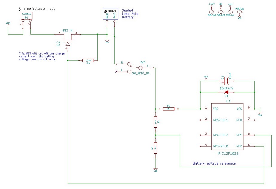
    Name:  SLA charge protection.jpg
Views: 1556
Size:  45.8 KB
    Last edited by Heckler; - 10th February 2014 at 04:21.
    Dwight
    These PIC's are like intricate puzzles just waiting for one to discover their secrets and MASTER their capabilities.

  11. #11
    Join Date
    Jul 2003
    Location
    Colorado Springs
    Posts
    4,959


    Did you find this post helpful? Yes | No

    Default Re: DT_Analog & 12F1822 internal voltage reference

    Defines are case sensitive.
    Change them to ...
    Code:
    define ADC_BITS 10            'set up the a/d converter
    define ADC_SAMPLEUS 50
    define ADC_CLOCK has no effect on enhanced core devices.
    You set the clock in the ADCON1 register, which you have already done.
    DT

  12. #12
    Join Date
    Oct 2009
    Location
    Utah, USA
    Posts
    427


    Did you find this post helpful? Yes | No

    Default Re: DT_Analog & 12F1822 internal voltage reference

    Boy do I have a RED face...

    I think my last post to another thread was telling them the same thing...

    quoting myself:
    Just make sure you enter any "DEFINE" statements as all CAPS.
    They are case sensistive.
    I guess I did not go looking there because some of this code was working as an 8bit AD earlier. I'm guessing that 8 bit is the default and the fact that I had define "adc_bits = 8" was ignored.

    Working as expected now

    So now how do I use the internal FVR to make an external A/D reading more accurate?
    And how do I go about calibrating each PIC's FVR value??

    Thanks Darrel
    Dwight
    These PIC's are like intricate puzzles just waiting for one to discover their secrets and MASTER their capabilities.

  13. #13
    Join Date
    Oct 2009
    Location
    Utah, USA
    Posts
    427


    Did you find this post helpful? Yes | No

    Default Re: DT_Analog & 12F1822 internal voltage reference

    Sheesh...
    Disregard my last two questions.
    It's been a while since I read the whole thread.

    I think my questions had already been answered.

    But I do have another question...
    Why is the maximum AD value only 65472 for 16-bit DT_Analog??

    similarly is the AD value range for 8 bit 0-255 ??
    and for 10 bit AD 0-1023 ??

    Sorry for the dumb questions, I don't get into this programming enough to understand some of the finer points.


    dwight
    Last edited by Heckler; - 10th February 2014 at 16:58.

  14. #14
    Join Date
    Oct 2009
    Location
    Utah, USA
    Posts
    427


    Did you find this post helpful? Yes | No

    Default Re: DT_Analog & 12F1822 internal voltage reference

    Ok,

    after looking at 65472 in binary 1111111111000000

    It appears that you have just shifted a 10 bit binary to the Left end of a 16 bit number.

    So then the AD value for a 16-bit DT_Analog can range from 0-65472 ??
    Therefore we get to take advantage of the extra 6 bits of resolution EXCEPT when the value goes over 65472 ??
    We just give up a little resolution to gain the extra (almost) 6 bits over a 10 bit AD ??

    and 8 bit range is still 0-255
    and 10 bit range is still 0-1023
    Last edited by Heckler; - 10th February 2014 at 17:14.
    Dwight
    These PIC's are like intricate puzzles just waiting for one to discover their secrets and MASTER their capabilities.

  15. #15
    Join Date
    Oct 2005
    Location
    Sweden
    Posts
    3,521


    Did you find this post helpful? Yes | No

    Default Re: DT_Analog & 12F1822 internal voltage reference

    Hi,
    I suggest you do a little reading on Darrels DT_Analog page, I think it answers both questions.

    /Henrik.

  16. #16
    Join Date
    Oct 2009
    Location
    Utah, USA
    Posts
    427


    Did you find this post helpful? Yes | No

    Default Re: DT_Analog & 12F1822 internal voltage reference

    Thanks Henrik,

    that link seems to support what my gray matter was trying to wrap around

    I had been to Darrels web site but couldn't figure out how to get past the home page.

    My hat is off to those who can take all these intricate details of these PIC's and put it into practical application for the rest of us.
    Dwight
    These PIC's are like intricate puzzles just waiting for one to discover their secrets and MASTER their capabilities.

  17. #17
    Join Date
    Oct 2009
    Location
    Utah, USA
    Posts
    427


    Did you find this post helpful? Yes | No

    Default Re: DT_Analog & 12F1822 internal voltage reference

    Darrel,
    More questions...

    In your sample code above why is the A/D conversion clock set to FRC??
    Does that mean some sort of external hardware RC oscillator?

    Can you please shed some light on choosing the A/D conversion clock?
    From your website example... it would seem that one should only choose FRC is if the PIC clock is running at 48MHz
    Name:  adclock.gif
Views: 1249
Size:  9.4 KB
    or does this table not apply to the 16F1822?

    Thanks
    Dwight
    These PIC's are like intricate puzzles just waiting for one to discover their secrets and MASTER their capabilities.

  18. #18
    Join Date
    Oct 2009
    Location
    Utah, USA
    Posts
    427


    Did you find this post helpful? Yes | No

    Default Re: DT_Analog & 12F1822 internal voltage reference

    So after doing some searching I found this... here... http://www.microcontrollerboard.com/...converter.html
    Name:  adclock.jpg
Views: 1196
Size:  11.9 KB

    so now my question is...
    Is FRC just another way of saying Fosc/1 ?
    Is it not the case that Fosc/2 or Fosc/8 also come from the internal RC oscillator??

    Or is it the case that if one is using an external clock source for the PIC that you can either choose to divide the external clock source by 2, 8 or 32 (in the above example) or use the internal RC clock (FRC) for AD even though the PIC is clocked form an external source??

    Finally so far I have not had a need to run my projects faster than 4MHz and I just use the internal clock. So what is the best/correct AD clock source to use?
    Is it correct to read from the table on Darrel's AD page... if the OSC is running at 4MHz the best/correct choice is to use Fosc/8 ?

    Sorry for dragging this out so much... just trying to understand a little better.
    Dwight
    These PIC's are like intricate puzzles just waiting for one to discover their secrets and MASTER their capabilities.

  19. #19
    Join Date
    Jul 2003
    Location
    Colorado Springs
    Posts
    4,959


    Did you find this post helpful? Yes | No

    Default Re: DT_Analog & 12F1822 internal voltage reference

    I don't think the enhanced cores were available yet when I wrote that page.
    The older chips had a minimum TAD of 1.6uS, but the newer ones have a minimum TAD of 1.0uS.

    So you could use the values in that table, but they will be off by 1 division from "Optimal" settings.

    If you look in the A/D section of the 1822 datasheet, you should see this table ...
    I've marked the best setting at each oscillator freq. in red.
    Put the matching ADCS bits into the ADCON1 register bits 4-6. DEFINE ADC_CLOCK does not have any effect on the enhanced core devices.

    Name:  1822_ADCS.jpg
Views: 1420
Size:  111.0 KB

    The FRC clock is an internal RC oscillator that is separate from the main internal oscillator (FOSC).
    It continues running even when the PIC is put to SLEEP.
    It can be used at any OSC. But the actual TAD period can be anywhere from 1.0 - 6.0uS.
    Last edited by Darrel Taylor; - 11th February 2014 at 17:31.
    DT

Similar Threads

  1. Fixed Voltage Reference
    By kduck63 in forum mel PIC BASIC Pro
    Replies: 8
    Last Post: - 20th April 2012, 11:27
  2. ADC with reference voltage
    By GoldStar in forum mel PIC BASIC Pro
    Replies: 4
    Last Post: - 20th May 2010, 21:01
  3. ADC - 2 channels but not same voltage reference - how to?
    By flotulopex in forum mel PIC BASIC Pro
    Replies: 2
    Last Post: - 25th November 2007, 19:03
  4. COMPARATOR - Voltage Reference settings
    By flotulopex in forum mel PIC BASIC Pro
    Replies: 1
    Last Post: - 9th October 2007, 07:06
  5. AD Negative Voltage reference
    By flotulopex in forum mel PIC BASIC Pro
    Replies: 4
    Last Post: - 28th June 2007, 15:01

Members who have read this thread : 2

You do not have permission to view the list of names.

Posting Permissions

  • You may not post new threads
  • You may not post replies
  • You may not post attachments
  • You may not edit your posts