

Hi All!
I would like to use the Memsic 2125 sensor just for pitch and roll tilt angles. Most code I have seen seems very complex. Does anyone have a link or the code in Picbasic for this sensor? Thanks, Ed


Hi All!
I would like to use the Memsic 2125 sensor just for pitch and roll tilt angles. Most code I have seen seems very complex. Does anyone have a link or the code in Picbasic for this sensor? Thanks, Ed

Calculating degrees from an accelerometer is rather involved. You need some trig functions. Looks like these guys did it with ArcCosine and ArcSine http://www.parallax.com/dl/docs/prod/acc/memsickit.pdf . Or it could be done with ArcTan: http://www.picbasic.co.uk/forum/cont...-axis-g-sensor (different sensor, but tilt degree math will work on any sensor)
This gentleman used the Memsic 2125 sensor, and his code might be a little easier, with less resolution. Check out his tilt code in the middle of his code at GetSensors:
http://www.picbasic.co.uk/forum/cont...-(open-source)
http://www.scalerobotics.com
Thanks Walter!
Yes I have looked at the code(s) you referenced and to be perfectly honest the code is completely confusing and way over my head. The spec sheet I believe says that the sensor puts out a square wave that varies in time so "Pulsin" would read the sensors outputs. Where I become completely lost is it would seem there would be a fairly simple conversion from pulse width to angle? Best, Ed
To make it easier, you could use a lookup table. Here is an example of one for the memsic for a basic stamp. http://www.parallax.com/Portals/0/Do...3/col/nv92.pdf .The table lookups only calculate on one axis, so they will not be as accurate as a 3 axis solution, but might be perfectly fine for your application.
http://www.scalerobotics.com
Thanks!
I guess where my confusion is that SubTech makes an automatic pitch controller (APC-3 and APC-4) that drives a servo to correct the pitch angle with the rear planes. You use the bow planes to change the pitch for up and down. Since the output is basically PWM and with pulsin you are measuring the pulse width then the code is very simple. Trueangle=((10*pulsewidth)+1500)/10. An up angle would be Displayangle = (TrueAngle -900)*2 while a down angle would be Displayangle = (900- Trueangle)*2. So it looks as if you could use a simple calculation to obtain the angle?
Hi Ed,
I am unclear where you got that formula. From what I have read, it seems a little too simple to work. What am I missing? The Memsic 2125 outputs in measurements of gravity, not angle.
http://www.scalerobotics.com
Hi Walter,
This is where I get confused. To measure a servo's angle you do a calculation based upon the pulse width (1ms-2ms with 1.5ms as center). From what I can see the 2125 gives a variable pulse width based upon the temperature difference between temperature sensors based upon the angle of the internal gas bubble. Therefore the 2125 output pulse width should be related to the tilt of a given axis?
![Name: 28017-Memsic2Axis-v2.0[1]_Page_1.jpg
Views: 2207
Size: 97.4 KB](https://www.picbasic.co.uk/forum/attachment.php?s=bf61873ed55be3d04abef4e346cc4aef&attachmentid=6505&d=1338665202)
I gather from the datasheet http://www.parallax.com/dl/docs/prod/acc/memsickit.pdf the 2125 is just an accelerometer, and will give the pulse output based on the G sensed, but not based on angle. Perhaps you don't need an angle, if you are just wanting to keep the nose of your sub pointed at 0 tilt.
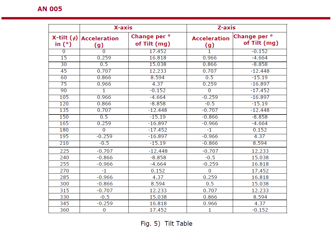
This spreadsheet sort of shows the correlation (or lack thereof) between angle and G sensed. It could be used to make a lookup table to determine angle.
http://www.scalerobotics.com
Thanks Walter!
I already have an Automatic Pitch Controller that keeps the sub level and just wished to display the pitch angle as well as the roll angle. Things like "look-up tables" are completely foreign to me and trig math just seemed to complex. Maybe I am just looking at the wrong type of sensor? I saw the electrolyte type and apparently they do not like DC. It also seems silly to buy another Automatic Pitch Controller just to read the roll angle. Best, Ed
Hi Ed,
I'm with you. There SHOULD be something like you suggest. There is in the higher ranges that's merged with 9dof type higher priced stuff. But what you want is simpler.
So you want a pitch and roll sensor that outputs in degrees. What type of interface would you like? Serial or i2c or other?
http://www.scalerobotics.com
Hi Walter,
Thank you for your input and assistance with this project. Years ago when I was working on a compass things were similar with requiring complex code and higher math which were not necessary as I later discovered. I have to believe that the people building robots must have a simple way to keep their robot "balanced". Again, going back to the Subtech APC-3 and 4 these Automatic Pitch Controllers which drive a servo were on the market long before the code using the "trig" include was created. My use is to take the outputs from the sensor store in in a variable to display on a "BOB-4" on screen display. The sub has a periscope camera which provides the video for a FPV with the subs operational data displayed. Best, Ed

Hi Ramius, Can you provide links to the equipment you are using? At least for the FPV stuff and the BOB-4? It will be intresting to see what kind of data it requires to add to the sub's operational data displayed.
-Bert
The glass is not half full or half empty, Its twice as big as needed for the job!
http://foamcasualty.com/ - Warbird R/C scratch building with foam!
Hi Ed,Originally Posted by Ramius

I suspect that the Subtech APC-3 or 4 may not really care about angle, and just looks at how far off a neutral horizon you are, adjusting the pitch accordingly (much like some simpler robots). It may use a lookup table of some sort to do this, or some math, or a combination of the two. From what I read about one of the sensors mentioned (in another forum) PitchControlStamp LR2 , it doesn't really state if it is working off a 1,2 or 3 axis accelerometer. As I mentioned earlier, a lookup table could get you close for angle. For example, at 75 degrees a (1 axis) pitch lookup table would start to get off by more than 3 degrees, and even more if there was any roll involved. This error goes up to about 10 degrees as you approach 90 degrees. And remember with some roll involved, it would be much higher error. Perhaps there is not much roll in a sub, I am not sure. If these are close enough, then certainly it can be done with a lookup table, and many on this site, including myself would be willing to help you with that. As for cost of on the market pitch controllers, even the Subtech parts look to be about $55 each, the LR2 $95 each, and both seem to only control 1 axis.
Looking up your ideal sensor made us realize there is a need for an inexpensive sensor that outputs an angle. I did find this one, and it fit the bill, all except for the inexpensive part: http://www.sparkfun.com/products/8656 .
We are making a similar sensor, giving an angle output for Pitch, Roll and a tilt compensated compass heading. But price will be much less. It should take about 4 weeks to get the PCB made and code finalized.
http://www.scalerobotics.com
Hi cncmachineguy,
Here is the link for the OSD http://www.decadenet.com/bob4/bob4.html . It allows 40 characters by 22 lines. In the past I looked at the OSD-232+ and it only allowed 30 columns by 12 rows. Have not yet finalized the goggles yet, there are a few considerations such a if they underscan the video or overscan and if I can shift the display on one display horizontally as this would allow for a "3-D" effect!
Walter, if you are playing with compasses then maybe look at http://www.robsonco.com/Dinsmore/Untitled_5.html .
Best, Ed
Hi Walter,I have looked and looked and looked at all this different information and it still has me very lost and confused. I need to calculate the PWM outputs to acceleration, then take the arcsine of the acceleration determine the angle of incination. I know you suggested using a look-up table and I have never done this before and not sure how it is done. Basically I am asking how is the code written in simple terms I can study. Thanks, Ed
Hi Ed,
If I were you, I'd use the Parallax Memsic 2125 example, as it is probably the easiest of what I have seen. It uses a lookup table and simple math to approximate the angle, with pretty good accuracy within the 0 to 45 degree range (but error will increase as roll increases, since a lookup table can only take one axis into account at a time).
Parallax shows a table for angle/g from Memsic:
Straight from the nv92.pdf example:
Now, we could take the easy route and use 62.35 as our conversion factor, but this would give us
an error at low tilt angles that we really don't need to tolerate. What we'll do, then, is work
backward from this data and determine the output from the 2125 at the angles specified in the
chart. Then we can use LOOKDOWN to compare the 2125 output to the chart and a LOOKUP
table to determine the proper tilt conversion factor.
Calculating the maximum g-force output for a given range is done by dividing the arc for a range
by its conversion factor. This will give us the maximum g-force output for that range.
10 ÷ 57.50 = 0.17391
20 ÷ 58.16 = 0.34387
30 ÷ 59.05 = 0.50804
40 ÷ 60.47 = 0.66148
50 ÷ 62.35 = 0.80192
Remember that the g-force output from the BASIC Stamp code is in 0.001g units, so we'll
multiply the results above by 1000 for use in a LOOKDOWN table. Let's look at the code that
converts g-force to tilt.
Here is some of the code, modified only slightly for Picbasic:
Code:xRaw VAR Word ' pulse width from Memsic 2125 xGForce VAR Word ' x axis g force (1000ths) xTilt VAR Word ' x axis tilt (100ths) idx VAR byte ' table index mult VAR Word ' multiplier - whole part frac VAR Word ' multiplier - fractional part HiPulse con 1 ' tells pulsin to look for highpulse, not lowpulse Read_X_Force: PULSIN PORTB.1, HiPulse, xRaw xRaw = xRaw * 2 ' g = ((t1 / 0.01) - 0.5) / 12.5% ' formula from data sheet xGForce = ((xRaw / 10) - 500) * 8 ' Modified for our PIC - Converts to 1/1000 g's RETURN Read_X_Tilt: GOSUB Read_X_Force ' tilt = g x k ' ' Select tilt conversion factor based on static ' G force. Table data derived from Memsic specs. LOOKDOWN2 ABS xGForce, <=[174, 344, 508, 661, 2000], idx ' above table are thousandths g results for 10,20,30,40 and max value degrees LOOKUP idx, [57, 58, 59, 60, 62], mult 'integer lookup LOOKUP2 idx, [32768, 10486, 2621, 30802, 22938], frac 'gets fractional result ' G Force is divided by 10 to prevent roll-over errors at end ' of range. Tilt is returned in 100ths degrees. ' Parallax explains fractional lookup like this: ' 65,536 * .16 (this is from the fractional part of 20 degree, 58.16 number) = 10486 xTilt = mult * (ABS xGForce / 10) + (frac ** (ABS xGForce / 10)) Check_SignX: IF (xGForce.Bit15 = 0) THEN XT_Exit ' if positive, skip xTilt = -xTilt ' correct for g force sign XT_Exit: RETURN
http://www.scalerobotics.com
Thanks Walter! You are the best! Ed
Hi Walter and everyone!
Okay so I corrected the code in the Read_X_Force as the "return" caused the program to stop and the formula said to divide by 8 not multiply. With the digital scope I was able to know the exact timing of the pulses. The catch is that the devide puts out a pulse reading from 1810 to 3132 so the formula does not work. I attached word files to show the code, what the pulse measurement is at level, what the code does with level and what the code does with the device at +90 degrees (up) and -90 degrees (down). The original code uses 10 ms and the scope says it is 9.9 ms so rather than x2 I made it x20 to divide by 99. The problem with the code seems to be with the 50% duty cycle value? Please let me know what you think. Thanks, Ed
Pulse Widths.doc
Tilt Code.doc
UP.doc
Level.doc
Down.doc
Ed, are you refering to the place in the formula where there was a /12.5% ? If so, this is simplified by *8.
See this part of the previously attached document:
"Since our T1 time is in microseconds and there are 1000 microseconds in a millisecond, we need
to multiply the T2 value and 0.5 by 1000 to adjust the equation. This makes the math easy for the
Stamp and gives us an output with a resolution of 0.001g. Finally, the divide by 12.5% part of the
equation is converted to multiplying by eight ( 1 / 0.125 = 8 ) – we couldn't ask for a value much
more convenient than that."
http://www.scalerobotics.com
Looking at your result for xRaw pulse (in your level.doc), and running through the formula, it looks to be correct using the original formula given:
Code:PULSIN PORTB.1, HiPulse, xRaw xRaw = xRaw * 2 ' g = ((t1 / 0.01) - 0.5) / 12.5% ' formula from data sheet xGForce = ((xRaw / 10) - 500) * 8 ' Modified for our PIC - Converts to 1/1000 g's
xRaw = 2472
xRaw * 2 = 4944
xRaw /10 = 494
494 - 500 = -6
-6 * 8 = -48 (-.048 g's which can probably be calibrated for.)
57.5*(-48/10) =274 hundredths degrees, or -2.74 degrees.
seems like its pretty close given the original equation. Since your total period is short, that might explain why its off a little bit. T2 was supposed to be 10ms (and is assumed as such in the code.)
I would try calibrating it using a -494 , instead of a -500 and see what you get.
Edit: I see now you are calibrating with the *20 and /99.
This method workes pretty good to 45 degrees or so. At 90 degrees, it obviously doesn't work very well, and is about 24 degrees off.
Last edited by ScaleRobotics; - 23rd June 2012 at 18:17.
http://www.scalerobotics.com
Hi Walter,
You are correct and just a minor "brain cramp" with the * vs /. With the logic analyzer results (Pulse Width.doc) the results showed a T1 of 502 which is why I used this number. The sensor document, 28017, says the "duty cycle" can be from 48.7% to 51.3% so the logic analyzer reading of 50.2% made sense. In the formula they use 50%. It is also assumed that the pulse timing is 10 ms which would be true if if the PWM signal were 100 hz. Again the logic analyzer show a frequency of 101 hz so the overall timing becomes 9.9 ms. Okay, both are minor corrections. You can not do a divide by 9.9 as it is not a whole number so to change the *2 to *20 allows the divide by 99 (9.9). Where I am having trouble with the formula is that if you point the sensor front edge down by 30-40 degrees then xRaw reading becomes about 414 which results in a number in the 65,000 range as 414 - 494 will give a result of -80. My best guess is that one would have to a lower number such as the 414 rather than 494 for the range of the sensor pointed down? Thanks, Ed
It sounds like its in the right range, if I am understanding it right.
414 - 494 = -80
-80 * 8 = 640, or .640 g's
~60 * (640/10) = ~ -3840 or negative 38.4 degrees
The ABS (absolutes) are used to keep the math working, while the check on xGForce.bit15 is used to detect if it is a negative number. I don't think you are overflowing with your * 20, but a quick check of the xRaw might be in order.
http://www.scalerobotics.com
Hey Walter!
Got it working! There was a line of code at the bottom XTilt = -XTilt that needed to be removed. The output from the sensor is in the 1800-2000 range so to multiply by 20 still keeps things under the 65536 limit so then a divide by 99 brings things back to "normal" range. Just as a "check" I bought a small digital level to use as a reference and there are errors over range of up to 3 degrees! Wish I had an ARCSIN function!
Great to hear!
In the Nuts and Volts article they handle the XTilt like this for printing:
But I am sure your solution works as well.Code:Display: DEBUG MoveTo, 0, 3 DEBUG "Raw Input... ", DEC (xRaw / 1000), ".", DEC3 xRaw, " ms", ClrRt, CR DEBUG "G Force..... ", (xGForce.Bit15 * 13 + " ") DEBUG DEC (ABS xGForce / 1000), ".", DEC3 (ABS xGForce), " g", ClrRt, CR DEBUG "X Tilt...... ", (xGForce.Bit15 * 13 + " ") DEBUG DEC (ABS xTilt / 100), ".", DEC2 (ABS xTilt), DegSym, ClrRt PAUSE 200 GOTO Main
http://www.scalerobotics.com
Thanks and here is the current temporary code. The plan is to take Read_Tiltx and Read_tilty and make it one subroutine for both the X and Y to conserve on the amount of code. I put a indicator (0 and 1) to show + and - angle for X and port and starboard for the Y. Best, Ed
'************************************************* ***************
'* Name : X-Y Tilt.BAS *
'* Author : Ed Cannady *
'* Notice : Copyright (c) 2012 Copyright (c) 2012 *
'* : All Rights Reserved *
'* Date : 6/17/2012 *
'* Version : 1.0 *
'* Notes : 16F628A and Memsic 2125 *
'* : *
'************************************************* ***************
include "Modedefs.bas"
' ** Set Xtal Value in mHz **
define OSC 20 ' Set Xtal Frequency
#CONFIG
__config _HS_OSC & _WDT_ON & _MCLRE_ON & _LVP_OFF & _CP_OFF
#endconfig
' ** Declare Pins Used **
CMCON= 7
input PortA.0 ' X Data is clocked on rising edge of this pin
input PortA.2 ' Y Data is clocked on rising edge of this pin
' ** Variables **
xRaw var word 'High Pulse width from Memsic 2125
xGForce var word ' x axis g force (1000ths)
xTilt var word ' x axis tilt (100ths)
xidx var byte 'Table index
xmult var word 'Multiplier - whole part
xfrac var word 'Multiplier - fractional part
xPosNeg var byte 'Positive angle or Negative angle flag
yRaw var word 'High Pulse width from Memsic 2125
yGforce var word ' x axis g force (1000ths)
yTilt var word ' x axis tilt (100ths)
yidx var byte 'Table index
ymult var word 'Multiplier - whole part
yfrac var word 'Multiplier - fractional part
yPosNeg var byte 'Positive angle or Negative angle flag
Read_Force:
pulsin PORTA.0, 1, xRaw
pulsin PORTA.2, 1, yRaw
xRaw = xRaw * 20
xGForce = (xRaw / 99 - 500) * 8 'xGForce = ((xRaw / 99) - 502) * 8 ' g = ((t1 / 0.01) - 0.5) / 12.5%
yRaw = yRaw * 20
yGforce = (yRaw / 99 - 487) * 8 'yGforce = ((xRaw / 99) - 502) * 8 ' g = ((t1 / 0.01) - 0.5) / 12.5%
Read_Tiltx: 'tilt = g x k Select tilt conversion factor based on static G force. Table data derived from Memsic specs.
lookdown2 abs xGForce, <=[174, 344, 508, 661, 2000], xidx ' Table is in thousandths g results for 10,20,30,40 and max value degrees
lookup xidx, [57, 58, 59, 60, 62], xmult 'integer lookup
lookup2 xidx, [32768, 10486, 2621, 30802, 22938], xfrac 'gets fractional result
xTilt = xmult * (abs xGForce / 10) + (xfrac ** (abs xGForce / 10))
Read_Tilty: 'tilt = g x k Select tilt conversion factor based on static G force. Table data derived from Memsic specs.
lookdown2 abs yGforce, <=[174, 344, 508, 661, 2000], yidx ' Table is in thousandths g results for 10,20,30,40 and max value degrees
lookup yidx, [57, 58, 59, 60, 62], ymult 'integer lookup
lookup2 yidx, [32768, 10486, 2621, 30802, 22938], yfrac 'gets fractional result
yTilt = ymult * (abs yGforce / 10) + (yfrac ** (abs yGforce / 10))
Check_SignX: 'Check the sign of X angle
if (xGForce.bit15 = 0) then XT_Exit ' if positive, skip correct for g force sign
xPosNeg = 0 ' If xPosNeg = 0 then the angle is negative (-)
gosub Check_SignY
XT_Exit:
xPosNeg = 1 ' If xPosNeg = 1 then the angle is positive (+)
Check_SignY: 'Check the sign of Y angle
if (yGforce.bit15 = 0) then YT_Exit ' if positive, skip correct for g force sign
yPosNeg = 0 ' If yPosNeg = 0 then the angle is negative (-)
gosub Read_Force
YT_Exit:
yPosNeg = 1 ' If yPosNeg = 1 then the angle is positive (+)
gosub Read_Force
 Members who have read this thread : 1
You do not have permission to view the list of names.
 Posting Permissions
Bookmarks