

A friend of mine had an issue with the cooling fans on one of his cars. He originally asked if I could just wire up a switch so he could turn the fans on/off with a switch. I thought this would work but what if he forgot to turn them on and the car would then overheat. So I decided to look into creating a circuit for him that would monitor the temperature of the coolant and turn the fans on/off respectively.
The coolant sensor on his car is just a thermistor that increases in resistance as the temperature rises. The car ECU provides a voltage divider circuit that then measures the voltage at the sensor. While gathering information about thermistors i concluded that there measured resistance on a graph is non-linear. When using the thermistor in a voltage-divider circuit the graph of the measured voltage becomes more linear. There are different reasons why car cooling fans do not turn on; faulty relay's, ECU's, sensor's, fan's, wiring, etc. The particular model of car he has [2000 Chevy Malibu] is notorious for having this problem. As far as I can see no one has solved the problem directly; it seems to be a problem of the manufacturer.
When connecting a OBDII scanner to the car I am still able to read the coolant sensors temperature. Using a voltmeter, we read the value at the sensor and noted what the temperature was on the OBDII scanner. He told me what temps he wanted the fans high/low to turn on/off. This initially seemed simple enough....so I thought.
Back at my home I decided I would use a PIC12F675 for the project; it was small and had ADC features. I remembered a long time ago I built a circuit for a very simple voltmeter, but it was using a BS2 module. After a little more research, I found a similar example on these forums for reading the voltage on a ADC pin. After a few tests everything seemed to work as it should. The values fluctuated initially, but after I set the VREF to VDD it seemed to stop. Next I etched circuit onto a copper-clad PCB. Now the fluctuation returned.
What I was wanting to know, is there a better way of reading the voltage using an ADC on the 16F675. Here is my code, and I also attached a picture of the schematic. The SEROUT portions will eventually be removed once develpment was complete. They were just used so I could test the circuit while at the car. The fan-relays on the car also have flyback-protection diodes.
Also when I inserted the PICBASIC code it changed the formatting, so everything that was supposed to be capitalized is not anymore.
Thanks, and sorry for the long-winded story.
Code:@ DEVICE pic12F675, INTRC_OSC_NOCLKOUT ' Internal Oscillator Define OSCCAL_1K 1 ' Calibrate internal oscillator ADCON0.7 = 1 ' Right justify result ADCON0.6 = 0 ' set Vref to VDD ANSEL = 001000 ' Set AN3 analog, rest digital CMCON = 7 ' disable analog comparator ' Define ADCIN parameters Define ADC_BITS 10 ' Set number of bits in result Define ADC_CLOCK 3 ' Set clock source (3=rc) Define ADC_SAMPLEUS 50 ' Set sampling time in uS sample_size var byte i var byte V_in Var Word V_total var word TX Var GPIO.5 mode VAR byte low_fan var GPIO.2 high_fan var GPIO.1 mode = 2 '// 2=T9600, 6=N9600 sample_size = 50 v_total = 0 V_in = 0 LOW low_fan LOW high_fan pause 500 serout TX, mode, [10,10] serout tx, mode, [10,13,"------------------", 10, 13] serout tx, mode, [ "ECT Fan-Controller", 10, 13] serout tx, mode, [ "------------------", 10, 13] main: gosub read_v gosub check_v gosub update_display goto main update_display: serout TX, mode, [#V_total,13] pause 1000 '// slight delay to lower flickering Return check_v: if V_total <= 201 then high low_fan '/ car test value 201 if V_total <= 181 then high high_fan '/ car test value 191 if V_total >= 211 then gosub fans_off '/ turn both fans off Return fans_off: low low_fan low high_fan return read_v: for i = 1 to sample_size pauseus 50 ADCIN 3, v_in ' Read channel 3 to V_in (0-1023) V_Total = (V_In + V_total) next i V_total = V_total/sample_size ' average the values V_Total = (V_total */ 500)>>2 ' Equates to: (V_in * 500)/1024 Return end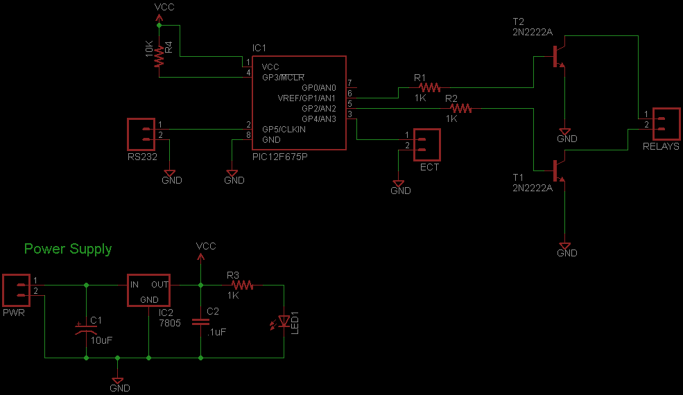


Bookmarks